
User's Manual
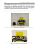
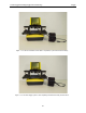
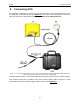
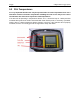
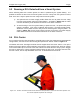
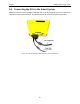
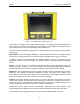
Table Of Contents
- 1 General Overview
- 2 Noggin Components
- 3 Noggin 100 Assembly
- 4 SmartCart Assembly
- 5 SmartTow Assembly
- 6 SmartHandle Assembly (Noggin 500 & 1000 only)
- 7 Rock Noggin Assembly (Noggin 500 & 1000 only)
- 8 Connecting GPS
- 9 Digital Video Logger (DVL)
- 10 Powering Up the System
- 11 Locate & Mark Mode
- 12 Survey & Map Mode
- 12.1 Survey & Map Menu
- 12.2 Data Acquisition
- 12.2.1 Replaying or Overwriting Data
- 12.2.2 Screen Overview
- 12.2.3 Position Information
- 12.2.4 Data Display
- 12.2.5 Section C - Menu
- 12.2.6 Gain
- 12.2.7 Collecting Data using the Odometer
- 12.2.8 Collecting Data in Free Run Mode
- 12.2.9 Collecting Data using the Trigger (or B) Button
- 12.2.10 Noggin Data Screens
- 12.2.11 Calib. (Calibration) Menu
- 12.2.12 Error Messages
- 12.3 Noggin Setup
- 12.4 Noggin File Management
- 12.5 Noggin Utilities
- 13 Troubleshooting
- 14 Care and Maintenance
- Appendix A Noggin Data file Format
- Appendix B Health & Safety Certification
- Appendix C GPR Emissions, Interference and Regulations
- Appendix D Instrument Interference
- Appendix E Safety Around Explosive Devices
- Appendix F Using the PXFER Cable and WinPXFER Software
- F1 Transferring Data to a PC using the PXFER Cable
- F1.1 Connecting the Digital Video Logger to a PC
- F1.2 PXFER Cable Types
- F1.3 Installing and Running the WinPXFER Program
- F1.4 Setting the DVL to the PXFER Cable Type
- F1.5 Transferring Noggin Data Buffer Files
- F1.6 Exporting Nogginplus Data
- F2 Transferring One or More Noggin PCX Files to an External PC using WinPXFER
- Appendix G GPR Glossaries

9-Digital Video Logger (DVL) Noggin
44
9.3 Running a DVL Detached from a Smart System
When collecting data with a Smart System, the DVL is powered by the system battery. It is
possible to detach the DVL from the Smart System and use it away from the system to review
data. There are 2 ways to power the DVL away from the Smart System:
1) The optional DVL to Power Supply Cable allows the user to power the DVL away
from the Smart System using the system battery. As shown in Figure 9-2, the cable
connects the battery to the 9-socket connector on the back of the DVL.
2) To avoid having to use the system battery to power the DVL, an optional AC power
supply is available. This, when combined with the DVL II to Power Supply Cable,
allows the user to power the DVL away from the Smart System using AC power. As
shown in Figure 9-3, the AC power supply connects to the DVL II to Power Supply
Cable which connects to the 9 socket connector on the back of the DVL.
9.4 DVL Carrier
For convenience during data acquisition, especially when using the SmartTow and SmartHandle
configurations, the DVL can be carried using the optional DVL Carrier shown in Figure 9-2.
The bottom of the DVL is designed to slide onto the support shelf on the DVL Carrier. Line up the
bottom of the DVL with the shelf and slide it back onto the shelf. Push the DVL back far enough
so that the flexible clip on the front of the shelf catches and holds the DVL firmly in place. Wiggle
the DVL to make sure it is firmly snapped in before letting go of the unit. To remove the DVL from
the DVL Carrier, flex the clip downward as the DVL is slid forward off of the shelf.
Figure: 9-2 The DVL and control module can be attached to the optional DVL Carrier for hands-free operation. The
DVL can be adjusted to optimize the view angle.