
User's Manual
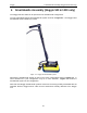
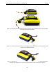
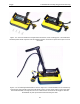
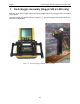
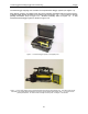
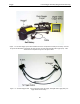
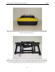
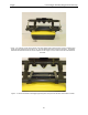
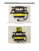
Table Of Contents
- 1 General Overview
- 2 Noggin Components
- 3 Noggin 100 Assembly
- 4 SmartCart Assembly
- 5 SmartTow Assembly
- 6 SmartHandle Assembly (Noggin 500 & 1000 only)
- 7 Rock Noggin Assembly (Noggin 500 & 1000 only)
- 8 Connecting GPS
- 9 Digital Video Logger (DVL)
- 10 Powering Up the System
- 11 Locate & Mark Mode
- 12 Survey & Map Mode
- 12.1 Survey & Map Menu
- 12.2 Data Acquisition
- 12.2.1 Replaying or Overwriting Data
- 12.2.2 Screen Overview
- 12.2.3 Position Information
- 12.2.4 Data Display
- 12.2.5 Section C - Menu
- 12.2.6 Gain
- 12.2.7 Collecting Data using the Odometer
- 12.2.8 Collecting Data in Free Run Mode
- 12.2.9 Collecting Data using the Trigger (or B) Button
- 12.2.10 Noggin Data Screens
- 12.2.11 Calib. (Calibration) Menu
- 12.2.12 Error Messages
- 12.3 Noggin Setup
- 12.4 Noggin File Management
- 12.5 Noggin Utilities
- 13 Troubleshooting
- 14 Care and Maintenance
- Appendix A Noggin Data file Format
- Appendix B Health & Safety Certification
- Appendix C GPR Emissions, Interference and Regulations
- Appendix D Instrument Interference
- Appendix E Safety Around Explosive Devices
- Appendix F Using the PXFER Cable and WinPXFER Software
- F1 Transferring Data to a PC using the PXFER Cable
- F1.1 Connecting the Digital Video Logger to a PC
- F1.2 PXFER Cable Types
- F1.3 Installing and Running the WinPXFER Program
- F1.4 Setting the DVL to the PXFER Cable Type
- F1.5 Transferring Noggin Data Buffer Files
- F1.6 Exporting Nogginplus Data
- F2 Transferring One or More Noggin PCX Files to an External PC using WinPXFER
- Appendix G GPR Glossaries

6-SmartHandle Assembly (Noggin 500 & 1000 only) Noggin
32
6.1 SmartHandle “Pull” Configuration
In some situations, conditions may dictate that pushing the SmartHandle system (Figure 6-1) is
not practical. An alternative configuration is to pull the SmartHandle system (Figure 6-7). To do
this, remove the 4 quick-release pins that hold the handle to the Noggin system, remove the
handle by pulling straight up and rotate the handle so that it faces the other direction. Then push
the handle down onto the Noggin as far as it will go and replace the 4 quick-release pins.
Figure: 6-7 In conditions where pushing the SmartHandle is difficult, it is possible to turn the handle
around and pull the system as shown.
6.2 Cable Connections
The DVL to Noggin cable is a Y-shaped cable with 3 connections; one to the Noggin sensor, one
to the DVL and one to the power supply (battery or AC).
Noggin Connection: The first connection was done in Figure 6-3 above, that is, the 37-pin
connector on the cable was attached to the 37-socket connector on the Noggin. A latch was
used to secure this connection.
From the Noggin, the DVL to Sensor Cable runs up the side of the SmartHandle. Use the Velcro
straps to secure the cable to the SmartHandle ensuring there is some slack in the cable near the
connection at the Noggin so, as the handle is pivots up and down there is no strain on the
connection (Figure 6-6).
DVL Connection: The second connection from the DVL to Sensor Cable is to the DVL. One end
of the Y-shaped cable has a 37-socket connector. This end plugs into the 37-pin connector on the
back of the DVL.
Power Connection: The third connection on the SmartHandle cable attaches to a power supply.
The round, 4-pin connector attaches to the battery. This configuration usually uses a belt battery.