
User's Manual
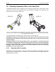
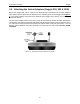
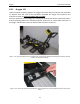
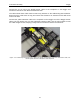
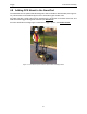
Table Of Contents
- 1 General Overview
- 2 Noggin Components
- 3 Noggin 100 Assembly
- 4 SmartCart Assembly
- 5 SmartTow Assembly
- 6 SmartHandle Assembly (Noggin 500 & 1000 only)
- 7 Rock Noggin Assembly (Noggin 500 & 1000 only)
- 8 Connecting GPS
- 9 Digital Video Logger (DVL)
- 10 Powering Up the System
- 11 Locate & Mark Mode
- 12 Survey & Map Mode
- 12.1 Survey & Map Menu
- 12.2 Data Acquisition
- 12.2.1 Replaying or Overwriting Data
- 12.2.2 Screen Overview
- 12.2.3 Position Information
- 12.2.4 Data Display
- 12.2.5 Section C - Menu
- 12.2.6 Gain
- 12.2.7 Collecting Data using the Odometer
- 12.2.8 Collecting Data in Free Run Mode
- 12.2.9 Collecting Data using the Trigger (or B) Button
- 12.2.10 Noggin Data Screens
- 12.2.11 Calib. (Calibration) Menu
- 12.2.12 Error Messages
- 12.3 Noggin Setup
- 12.4 Noggin File Management
- 12.5 Noggin Utilities
- 13 Troubleshooting
- 14 Care and Maintenance
- Appendix A Noggin Data file Format
- Appendix B Health & Safety Certification
- Appendix C GPR Emissions, Interference and Regulations
- Appendix D Instrument Interference
- Appendix E Safety Around Explosive Devices
- Appendix F Using the PXFER Cable and WinPXFER Software
- F1 Transferring Data to a PC using the PXFER Cable
- F1.1 Connecting the Digital Video Logger to a PC
- F1.2 PXFER Cable Types
- F1.3 Installing and Running the WinPXFER Program
- F1.4 Setting the DVL to the PXFER Cable Type
- F1.5 Transferring Noggin Data Buffer Files
- F1.6 Exporting Nogginplus Data
- F2 Transferring One or More Noggin PCX Files to an External PC using WinPXFER
- Appendix G GPR Glossaries

Noggin 4-SmartCart Assembly
15
4.6 Attach the Digital Video Logger (DVL)
The bottom of the Digital Video Logger is designed to slide onto the support shelf attached to the
SmartCart (Figure 4-14). Line up the bottom of the DVL with the shelf and slide it back onto the
shelf. Push the DVL back far enough so that the flexible clip on the front of the shelf catches and
holds the DVL firmly in place. Wiggle the DVL to make sure it is firmly snapped in before letting
go of the unit. To remove the DVL from the SmartCart, flex the clip downward as the DVL is slid
forward off of the shelf.
Figure: 4-14 Attaching the digital video logger (DVL). Step 1: Depress flexible clip. Step 2: Slide DVL onto shelf.
The DVL can be pivoted to adjust the view angle. If it is difficult to pivot the DVL, slightly loosen
the hand screws on the bottom of the support shelf.
Once the DVL is in place, attach the cable with the 37-socket female D-connector to the 37-pin
receptacle on the back of the Digital Video Logger. This attachment can be secured with the
latch.