
User's Manual
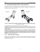
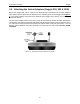
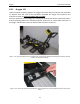
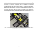
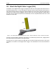
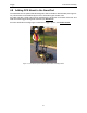
Table Of Contents
- 1 General Overview
- 2 Noggin Components
- 3 Noggin 100 Assembly
- 4 SmartCart Assembly
- 5 SmartTow Assembly
- 6 SmartHandle Assembly (Noggin 500 & 1000 only)
- 7 Rock Noggin Assembly (Noggin 500 & 1000 only)
- 8 Connecting GPS
- 9 Digital Video Logger (DVL)
- 10 Powering Up the System
- 11 Locate & Mark Mode
- 12 Survey & Map Mode
- 12.1 Survey & Map Menu
- 12.2 Data Acquisition
- 12.2.1 Replaying or Overwriting Data
- 12.2.2 Screen Overview
- 12.2.3 Position Information
- 12.2.4 Data Display
- 12.2.5 Section C - Menu
- 12.2.6 Gain
- 12.2.7 Collecting Data using the Odometer
- 12.2.8 Collecting Data in Free Run Mode
- 12.2.9 Collecting Data using the Trigger (or B) Button
- 12.2.10 Noggin Data Screens
- 12.2.11 Calib. (Calibration) Menu
- 12.2.12 Error Messages
- 12.3 Noggin Setup
- 12.4 Noggin File Management
- 12.5 Noggin Utilities
- 13 Troubleshooting
- 14 Care and Maintenance
- Appendix A Noggin Data file Format
- Appendix B Health & Safety Certification
- Appendix C GPR Emissions, Interference and Regulations
- Appendix D Instrument Interference
- Appendix E Safety Around Explosive Devices
- Appendix F Using the PXFER Cable and WinPXFER Software
- F1 Transferring Data to a PC using the PXFER Cable
- F1.1 Connecting the Digital Video Logger to a PC
- F1.2 PXFER Cable Types
- F1.3 Installing and Running the WinPXFER Program
- F1.4 Setting the DVL to the PXFER Cable Type
- F1.5 Transferring Noggin Data Buffer Files
- F1.6 Exporting Nogginplus Data
- F2 Transferring One or More Noggin PCX Files to an External PC using WinPXFER
- Appendix G GPR Glossaries

Noggin 4-SmartCart Assembly
11
4.5 Attaching the Noggin to the SmartCart
The Noggin is attached to the cart with the long axis of the Noggin unit parallel to the wheels on
the cart (see Figure 4-9 and Figure 4-10). Ensure the 37 socket female electrical receptacle on
the Noggin faces the back of the cart so that the cable on the cart will reach the receptacle.
4.5.1 Noggin 250
Remove the Clevis pins from the swivel adapters. Now, on the bottom of the cart, locate the 4
oval, moveable hangers suspended from the frame of the cart (see Figure 4-9). Notice that each
hanger has a hole in it. To attach the Noggin 250 to the cart, place each hanger into the slot on
the top of the swivel adapters, line up the holes and insert the Clevis pin.
Figure: 4-9 Attaching the Noggin 250 to the SmartCart.
Connect the 37 pin end of the Noggin-to-DVL cable to the receptacle on the Noggin and secure
this attachment with the latch.