
User's Manual
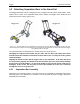
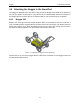
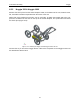
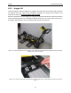
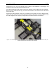
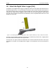
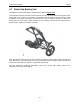
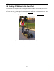
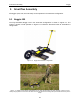
Table Of Contents
- 1 General Overview
- 2 Noggin Components
- 3 Noggin 100 Assembly
- 4 SmartCart Assembly
- 5 SmartTow Assembly
- 6 SmartHandle Assembly (Noggin 500 & 1000 only)
- 7 Rock Noggin Assembly (Noggin 500 & 1000 only)
- 8 Connecting GPS
- 9 Digital Video Logger (DVL)
- 10 Powering Up the System
- 11 Locate & Mark Mode
- 12 Survey & Map Mode
- 12.1 Survey & Map Menu
- 12.2 Data Acquisition
- 12.2.1 Replaying or Overwriting Data
- 12.2.2 Screen Overview
- 12.2.3 Position Information
- 12.2.4 Data Display
- 12.2.5 Section C - Menu
- 12.2.6 Gain
- 12.2.7 Collecting Data using the Odometer
- 12.2.8 Collecting Data in Free Run Mode
- 12.2.9 Collecting Data using the Trigger (or B) Button
- 12.2.10 Noggin Data Screens
- 12.2.11 Calib. (Calibration) Menu
- 12.2.12 Error Messages
- 12.3 Noggin Setup
- 12.4 Noggin File Management
- 12.5 Noggin Utilities
- 13 Troubleshooting
- 14 Care and Maintenance
- Appendix A Noggin Data file Format
- Appendix B Health & Safety Certification
- Appendix C GPR Emissions, Interference and Regulations
- Appendix D Instrument Interference
- Appendix E Safety Around Explosive Devices
- Appendix F Using the PXFER Cable and WinPXFER Software
- F1 Transferring Data to a PC using the PXFER Cable
- F1.1 Connecting the Digital Video Logger to a PC
- F1.2 PXFER Cable Types
- F1.3 Installing and Running the WinPXFER Program
- F1.4 Setting the DVL to the PXFER Cable Type
- F1.5 Transferring Noggin Data Buffer Files
- F1.6 Exporting Nogginplus Data
- F2 Transferring One or More Noggin PCX Files to an External PC using WinPXFER
- Appendix G GPR Glossaries

Noggin 4-SmartCart Assembly
9
4.3 Attaching Separation Bars to the SmartCart
The Noggin SmartCart can be configured to carry a Noggin 100, 250, 500 or 1000 system. Each
system has a unique set of separation bars used to attach the Noggin to the SmartCart and
suspend it over the surface (Figure 4-7).
Figure: 4-7 The separation bars are attached to the SmartCart to carry the Noggin. Each Noggin system (100, 250,
500 and 1000) has a unique set of separation bars; the Noggin 250 separation bars are shown on the left and Noggin
100 separation bars on the right.
The separation bars are attached to the SmartCart by four thumb screws.
Changing the support arms should only be done after the DVL and battery have been
detached from the SmartCart, otherwise the back half of the cart may fall to the ground
and be damaged.
Aligning the thumb screws and the support arm is very important. If the hole and insert
are not perfectly aligned, the thumb screw will bind after only half a turn and will damage
the insert by cross-threading it. As well, if the thumb screw is forced to turn it will also be
damaged. If this occurs, the only way to correct this problem is to then run a 10-32 tap
through the insert to re-tap the hole.
4.3.1 Separation Bar Assembly
Depending on the Noggin system, it may be necessary to assemble the separation bars before
attaching them to the SmartCart. For details, see the separate document “Noggin SmartCart
Separation Bar Assembly”.
Noggin 100
Noggin 250