
User's Manual
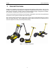
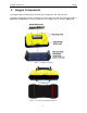
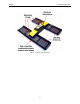
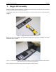
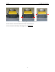
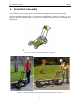
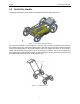
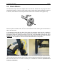
Table Of Contents
- 1 General Overview
- 2 Noggin Components
- 3 Noggin 100 Assembly
- 4 SmartCart Assembly
- 5 SmartTow Assembly
- 6 SmartHandle Assembly (Noggin 500 & 1000 only)
- 7 Rock Noggin Assembly (Noggin 500 & 1000 only)
- 8 Connecting GPS
- 9 Digital Video Logger (DVL)
- 10 Powering Up the System
- 11 Locate & Mark Mode
- 12 Survey & Map Mode
- 12.1 Survey & Map Menu
- 12.2 Data Acquisition
- 12.2.1 Replaying or Overwriting Data
- 12.2.2 Screen Overview
- 12.2.3 Position Information
- 12.2.4 Data Display
- 12.2.5 Section C - Menu
- 12.2.6 Gain
- 12.2.7 Collecting Data using the Odometer
- 12.2.8 Collecting Data in Free Run Mode
- 12.2.9 Collecting Data using the Trigger (or B) Button
- 12.2.10 Noggin Data Screens
- 12.2.11 Calib. (Calibration) Menu
- 12.2.12 Error Messages
- 12.3 Noggin Setup
- 12.4 Noggin File Management
- 12.5 Noggin Utilities
- 13 Troubleshooting
- 14 Care and Maintenance
- Appendix A Noggin Data file Format
- Appendix B Health & Safety Certification
- Appendix C GPR Emissions, Interference and Regulations
- Appendix D Instrument Interference
- Appendix E Safety Around Explosive Devices
- Appendix F Using the PXFER Cable and WinPXFER Software
- F1 Transferring Data to a PC using the PXFER Cable
- F1.1 Connecting the Digital Video Logger to a PC
- F1.2 PXFER Cable Types
- F1.3 Installing and Running the WinPXFER Program
- F1.4 Setting the DVL to the PXFER Cable Type
- F1.5 Transferring Noggin Data Buffer Files
- F1.6 Exporting Nogginplus Data
- F2 Transferring One or More Noggin PCX Files to an External PC using WinPXFER
- Appendix G GPR Glossaries

4-SmartCart Assembly Noggin
8
4.2 Attach Wheels
The SmartCart may have been shipped without the wheels attached or they may have been
removed for storage. If this is the case, find the axle for each wheel, press the button on the end
of the axle, and insert the axle through the wheel and into the SmartCart frame (Figure 4-5).
Figure: 4-5 Attaching the wheel.
With the system unfolded, make sure the small odometer wheel makes good contact with the
side of the cart wheel.
If the odometer contact with the wheel is too loose, the odometer wheel may slip, resulting in
erroneous position measurements. If the odometer wheel seems loose, use a ¼ inch Allen
(hexagonal) wrench to loosen the screws on the side of the odometer and pivot the entire
odometer unit until the small odometer wheel makes good contact with the side of the cart wheel
(Figure 4-6
). Then tighten the screws to lock the odometer wheel in this position.
Figure: 4-6 If the odometer wheel does not make good contact with the wheel, use a hexagonal wrench to loosen the
2 screws (left) and pivot the odometer outward so when the wheel is attached the odometer rolls continuously (right).
After this has been done, it will be necessary to re-calibrate the odometer (Section 12.5.2
Odometer Calibration).