
User's Manual


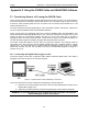
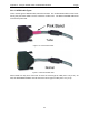
Table Of Contents
- 1 General Overview
- 2 Noggin Components
- 3 Noggin 100 Assembly
- 4 SmartCart Assembly
- 5 SmartTow Assembly
- 6 SmartHandle Assembly (Noggin 500 & 1000 only)
- 7 Rock Noggin Assembly (Noggin 500 & 1000 only)
- 8 Connecting GPS
- 9 Digital Video Logger (DVL)
- 10 Powering Up the System
- 11 Locate & Mark Mode
- 12 Survey & Map Mode
- 12.1 Survey & Map Menu
- 12.2 Data Acquisition
- 12.2.1 Replaying or Overwriting Data
- 12.2.2 Screen Overview
- 12.2.3 Position Information
- 12.2.4 Data Display
- 12.2.5 Section C - Menu
- 12.2.6 Gain
- 12.2.7 Collecting Data using the Odometer
- 12.2.8 Collecting Data in Free Run Mode
- 12.2.9 Collecting Data using the Trigger (or B) Button
- 12.2.10 Noggin Data Screens
- 12.2.11 Calib. (Calibration) Menu
- 12.2.12 Error Messages
- 12.3 Noggin Setup
- 12.4 Noggin File Management
- 12.5 Noggin Utilities
- 13 Troubleshooting
- 14 Care and Maintenance
- Appendix A Noggin Data file Format
- Appendix B Health & Safety Certification
- Appendix C GPR Emissions, Interference and Regulations
- Appendix D Instrument Interference
- Appendix E Safety Around Explosive Devices
- Appendix F Using the PXFER Cable and WinPXFER Software
- F1 Transferring Data to a PC using the PXFER Cable
- F1.1 Connecting the Digital Video Logger to a PC
- F1.2 PXFER Cable Types
- F1.3 Installing and Running the WinPXFER Program
- F1.4 Setting the DVL to the PXFER Cable Type
- F1.5 Transferring Noggin Data Buffer Files
- F1.6 Exporting Nogginplus Data
- F2 Transferring One or More Noggin PCX Files to an External PC using WinPXFER
- Appendix G GPR Glossaries

Noggin Appendix F - Using the PXFER Cable and WinPXFER Software
F-1
Appendix F Using the PXFER Cable and WinPXFER Software
F1 Transferring Data to a PC using the PXFER Cable
There are two methods available to transfer data files from the DVL to a PC. The usual method is
to save the data to the removable compact flash drive that is accessible using the door on the top
of the DVL. After powering down the DVL, this drive can be removed and inserted into a card
reader attached to a PC.
The other method of transferring data files to a PC, described in detail in this section, requires the
use of the optional PXFER cable and WinPXFER software.
There are two ways of transferring data to PC using the PXFER cable and WinPXFER. This
section describes transferring all data files to a PC. The other method is to transfer one or more
screens of data as a single PCX graphics file (see F2: p.F-6). This other type of transfer is
appropriate when the user wants to transfer a small amount of data to an external computer for
use with third-party graphics software packages like Microsoft Paint and Word.
To transfer all the data buffers from the DVL to an external computer, the computer must be
connected to the DVL using the special parallel XFER cable that is supplied with the system
(Section F1.1: p.1). Note that this is a special cable and standard 25 pin to 25 pin or Laplink
cables will not work. As well, the computer must have the WinPXFER program running on it
(Section F1.3: p.3).
F1.1 Connecting the Digital Video Logger to a PC
The Smart System comes with a separate cable called the parallel XFER cable. This cable is
designed to connect the DVL to an external computer.
Figure F-1: Parallel XFER cable (CABL0023) connections
The 2 connections that must be made before attempting to transfer data are:
1) Attach the 25 socket parallel connector to the 25 socket parallel port on back of the
Digital Video Logger, and
2) Attach the 25 socket parallel connector the parallel port of the external computer.
WARNING: To avoid damaging any of the components, turn off the DVL and computer
before making any of these connections.