
User's Manual
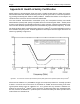
Table Of Contents
- 1 General Overview
- 2 Noggin Components
- 3 Noggin 100 Assembly
- 4 SmartCart Assembly
- 5 SmartTow Assembly
- 6 SmartHandle Assembly (Noggin 500 & 1000 only)
- 7 Rock Noggin Assembly (Noggin 500 & 1000 only)
- 8 Connecting GPS
- 9 Digital Video Logger (DVL)
- 10 Powering Up the System
- 11 Locate & Mark Mode
- 12 Survey & Map Mode
- 12.1 Survey & Map Menu
- 12.2 Data Acquisition
- 12.2.1 Replaying or Overwriting Data
- 12.2.2 Screen Overview
- 12.2.3 Position Information
- 12.2.4 Data Display
- 12.2.5 Section C - Menu
- 12.2.6 Gain
- 12.2.7 Collecting Data using the Odometer
- 12.2.8 Collecting Data in Free Run Mode
- 12.2.9 Collecting Data using the Trigger (or B) Button
- 12.2.10 Noggin Data Screens
- 12.2.11 Calib. (Calibration) Menu
- 12.2.12 Error Messages
- 12.3 Noggin Setup
- 12.4 Noggin File Management
- 12.5 Noggin Utilities
- 13 Troubleshooting
- 14 Care and Maintenance
- Appendix A Noggin Data file Format
- Appendix B Health & Safety Certification
- Appendix C GPR Emissions, Interference and Regulations
- Appendix D Instrument Interference
- Appendix E Safety Around Explosive Devices
- Appendix F Using the PXFER Cable and WinPXFER Software
- F1 Transferring Data to a PC using the PXFER Cable
- F1.1 Connecting the Digital Video Logger to a PC
- F1.2 PXFER Cable Types
- F1.3 Installing and Running the WinPXFER Program
- F1.4 Setting the DVL to the PXFER Cable Type
- F1.5 Transferring Noggin Data Buffer Files
- F1.6 Exporting Nogginplus Data
- F2 Transferring One or More Noggin PCX Files to an External PC using WinPXFER
- Appendix G GPR Glossaries

Noggin Appendix A - Noggin Data file Format
A-1
Appendix A Noggin Data file Format
Noggin data consists of two files, a Header file and a Data file. The files have the same name but
different extensions. The format details of these files are given below.
Header (.HD) File:
The header file, identified by the file extension .HD, is an ASCII file. An example is shown below.
The heading identifies what each piece of information represents.
1234
Data Collected with Noggin Plus
12/10/2000
NUMBER OF TRACES = 220
NUMBER OF PTS/TRC = 156
TIMEZERO AT POINT = 31
TOTAL TIME WINDOW = 62
STARTING POSITION = 0.0000
FINAL POSITION = 10.9500
STEP SIZE USED = 0.0500
POSITION UNITS = m
NOMINAL FREQUENCY = 250.00
ANTENNA SEPARATION = 0.3048
PULSER VOLTAGE (V) = 100
NUMBER OF STACKS = 4
SURVEY MODE = Reflection
This file can be read and/or printed using any Word Processor.
Data (.DT1) File:
The data file contains as many records as there are traces. Each record in turn consists of a
header section and a data section. The header section consists of an array of 25 real*4 numbers
and a string of 28 characters which is used for annotation. The 25 element real array contains the
following information:
Item # Description
1 Trace number
2Position
3 Number of points per trace
4 Topographic data, if available
5 (not used)
6 # bytes/point (always 2 for Rev 3 firmware)
7 Time Window
8 # of stacks
9-10 reserved for GPS X position (double*8 number)
11-12 reserved for GPS Y position (double*8 number)
13-14 reserved for GPS Z position (double*8 number)
15 reserved for receiver x position