
User's Manual
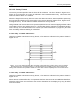
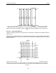

Table Of Contents
- 1 General Overview
- 2 Noggin Components
- 3 Noggin 100 Assembly
- 4 SmartCart Assembly
- 5 SmartTow Assembly
- 6 SmartHandle Assembly (Noggin 500 & 1000 only)
- 7 Rock Noggin Assembly (Noggin 500 & 1000 only)
- 8 Connecting GPS
- 9 Digital Video Logger (DVL)
- 10 Powering Up the System
- 11 Locate & Mark Mode
- 12 Survey & Map Mode
- 12.1 Survey & Map Menu
- 12.2 Data Acquisition
- 12.2.1 Replaying or Overwriting Data
- 12.2.2 Screen Overview
- 12.2.3 Position Information
- 12.2.4 Data Display
- 12.2.5 Section C - Menu
- 12.2.6 Gain
- 12.2.7 Collecting Data using the Odometer
- 12.2.8 Collecting Data in Free Run Mode
- 12.2.9 Collecting Data using the Trigger (or B) Button
- 12.2.10 Noggin Data Screens
- 12.2.11 Calib. (Calibration) Menu
- 12.2.12 Error Messages
- 12.3 Noggin Setup
- 12.4 Noggin File Management
- 12.5 Noggin Utilities
- 13 Troubleshooting
- 14 Care and Maintenance
- Appendix A Noggin Data file Format
- Appendix B Health & Safety Certification
- Appendix C GPR Emissions, Interference and Regulations
- Appendix D Instrument Interference
- Appendix E Safety Around Explosive Devices
- Appendix F Using the PXFER Cable and WinPXFER Software
- F1 Transferring Data to a PC using the PXFER Cable
- F1.1 Connecting the Digital Video Logger to a PC
- F1.2 PXFER Cable Types
- F1.3 Installing and Running the WinPXFER Program
- F1.4 Setting the DVL to the PXFER Cable Type
- F1.5 Transferring Noggin Data Buffer Files
- F1.6 Exporting Nogginplus Data
- F2 Transferring One or More Noggin PCX Files to an External PC using WinPXFER
- Appendix G GPR Glossaries

Noggin 12-Survey & Map Mode
107
The End String option allows the user to fill in the 5 character GPS prefix. Use the Left and Right
buttons to move left or right to different characters in the string. The currently selected character
will have an “^” under it. To change the letter of the current character, use the Next button to
change it to the next letter in the alphabet and the Previous button to change it to the previous
letter in the alphabet. Using these keys all 5 characters can be filled in with the necessary GPS
End String.
See the GPS Receiver User’s Guide for details on how to set up the receiver to output specific
NMEA strings or groups of NMEA strings.
System Test #1
After all the settings above have been input and the GPS receiver is attached to the serial port on
the DVL, the user can test that the DVL is receiving the GPS output by using the Test option.
If the NMEA strings are successfully being read by the DVL they will appear on the DVL screen.
This is a good time to note the prefix of the last NMEA string in the list and input it in the End
String setting above.
If the NMEA strings do not appear, check that the port settings are correct. It is also possible that
a crossover cable is required between the output cable of the GPS receiver and the serial port on
the DVL.
System Test #2
Once the GPS system is running successfully, System Test #2 can be used to graphically display
the GPS data. This screen displays the GPS Time, Latitude, Longitude and Altitude as well as
other values indicating the accuracy of the GPS reading. The GPS position is also displayed in a
square that can be Zoomed from 2 metres square to 16384 metres square.
12.3.6 Set Defaults
To reset all the parameter settings back to the factory default settings press the 6 button (labelled
Set Defaults).