
User's Manual
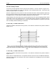
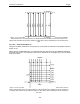


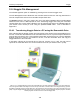
Table Of Contents
- 1 General Overview
- 2 Noggin Components
- 3 Noggin 100 Assembly
- 4 SmartCart Assembly
- 5 SmartTow Assembly
- 6 SmartHandle Assembly (Noggin 500 & 1000 only)
- 7 Rock Noggin Assembly (Noggin 500 & 1000 only)
- 8 Connecting GPS
- 9 Digital Video Logger (DVL)
- 10 Powering Up the System
- 11 Locate & Mark Mode
- 12 Survey & Map Mode
- 12.1 Survey & Map Menu
- 12.2 Data Acquisition
- 12.2.1 Replaying or Overwriting Data
- 12.2.2 Screen Overview
- 12.2.3 Position Information
- 12.2.4 Data Display
- 12.2.5 Section C - Menu
- 12.2.6 Gain
- 12.2.7 Collecting Data using the Odometer
- 12.2.8 Collecting Data in Free Run Mode
- 12.2.9 Collecting Data using the Trigger (or B) Button
- 12.2.10 Noggin Data Screens
- 12.2.11 Calib. (Calibration) Menu
- 12.2.12 Error Messages
- 12.3 Noggin Setup
- 12.4 Noggin File Management
- 12.5 Noggin Utilities
- 13 Troubleshooting
- 14 Care and Maintenance
- Appendix A Noggin Data file Format
- Appendix B Health & Safety Certification
- Appendix C GPR Emissions, Interference and Regulations
- Appendix D Instrument Interference
- Appendix E Safety Around Explosive Devices
- Appendix F Using the PXFER Cable and WinPXFER Software
- F1 Transferring Data to a PC using the PXFER Cable
- F1.1 Connecting the Digital Video Logger to a PC
- F1.2 PXFER Cable Types
- F1.3 Installing and Running the WinPXFER Program
- F1.4 Setting the DVL to the PXFER Cable Type
- F1.5 Transferring Noggin Data Buffer Files
- F1.6 Exporting Nogginplus Data
- F2 Transferring One or More Noggin PCX Files to an External PC using WinPXFER
- Appendix G GPR Glossaries

12-Survey & Map Mode Noggin
104
Mode
There are three GPS modes available:
1) Off mode means that a GPS receiver is not connected to the DVL so no GPS
information is being logged. This should be the setting if you do not have a GPS
receiver.
2) Reading every x traces mode means that every time the Noggin collects a user-
defined number of traces of GPR data, a data string of GPS information will be added
to a file. This file has the same name as the data file i.e. LINE6, but with a GPS
extension. This file can be accessed after transferring the GPR data files to an
external PC (see Section 12.4.1: p.108).
For example, if the number of traces is set to 1, the LINE6.GPS may look like this:
Trace #1 at position 0.00
$GPGGA,134713.00,4338.221086,N,07938.421365,W,2,06,2.1,152.51,M,-35.09,M,5.0,0118*79
$GPVTG,34.0,T,,,001.4,N,002.5,K,D*70
$GPGSA,A,3,30,26,10,13,24,06,,,,,,,4.2,2.1,3.6*36
Trace #2 at position 0.05
$GPGGA,134713.00,4338.221086,N,07938.421365,W,2,06,2.1,152.51,M,-35.09,M,5.0,0118*79
$GPVTG,34.0,T,,,001.4,N,002.5,K,D*70
$GPGSA,A,3,30,26,10,13,24,06,,,,,,,4.2,2.1,3.6*36
Trace #3 at position 0.10
$GPGGA,134713.00,4338.221086,N,07938.421365,W,2,06,2.1,152.51,M,-35.09,M,5.0,0118*79
$GPVTG,34.0,T,,,001.4,N,002.5,K,D*70
$GPGSA,A,3,30,26,10,13,24,06,,,,,,,4.2,2.1,3.6*36
Trace #4 at position 0.15
$GPGGA,134713.00,4338.221086,N,07938.421365,W,2,06,2.1,152.51,M,-35.09,M,5.0,0118*79
$GPVTG,34.0,T,,,001.4,N,002.5,K,D*70
$GPGSA,A,3,30,26,10,13,24,06,,,,,,,4.2,2.1,3.6*36
Note that when the Reading per Trace option is on, it is still possible to add fiducial markers to
the GPS file. These will appear as F1, F2 etc. between the trace numbers. For example, a
portion of LINE6.GPS may look like this:
Trace #85 at position 4.20
$GPGGA,134850.00,4338.204868,N,07938.429003,W,2,06,2.1,152.60,M,-35.09,M,4.2,0118*74
$GPVTG,152.6,T,,,002.3,N,004.3,K,D*43
$GPGSA,A,3,30,26,10,13,24,06,,,,,,,4.2,2.1,3.7*37
F1
$GPGGA,134850.00,4338.204868,N,07938.429003,W,2,06,2.1,152.60,M,-35.09,M,4.2,0118*74
$GPVTG,152.6,T,,,002.3,N,004.3,K,D*43
$GPGSA,A,3,30,26,10,13,24,06,,,,,,,4.2,2.1,3.7*37
Trace #86 at position 4.25
$GPGGA,134851.00,4338.204362,N,07938.428362,W,2,06,2.1,152.40,M,-35.09,M,5.2,0118*72
$GPVTG,136.9,T,,,002.8,N,005.2,K,D*45
$GPGSA,A,3,30,26,10,13,24,06,,,,,,,4.2,2.1,3.7*37