
User's Manual
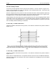
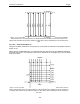

Table Of Contents
- 1 General Overview
- 2 Noggin Components
- 3 Noggin 100 Assembly
- 4 SmartCart Assembly
- 5 SmartTow Assembly
- 6 SmartHandle Assembly (Noggin 500 & 1000 only)
- 7 Rock Noggin Assembly (Noggin 500 & 1000 only)
- 8 Connecting GPS
- 9 Digital Video Logger (DVL)
- 10 Powering Up the System
- 11 Locate & Mark Mode
- 12 Survey & Map Mode
- 12.1 Survey & Map Menu
- 12.2 Data Acquisition
- 12.2.1 Replaying or Overwriting Data
- 12.2.2 Screen Overview
- 12.2.3 Position Information
- 12.2.4 Data Display
- 12.2.5 Section C - Menu
- 12.2.6 Gain
- 12.2.7 Collecting Data using the Odometer
- 12.2.8 Collecting Data in Free Run Mode
- 12.2.9 Collecting Data using the Trigger (or B) Button
- 12.2.10 Noggin Data Screens
- 12.2.11 Calib. (Calibration) Menu
- 12.2.12 Error Messages
- 12.3 Noggin Setup
- 12.4 Noggin File Management
- 12.5 Noggin Utilities
- 13 Troubleshooting
- 14 Care and Maintenance
- Appendix A Noggin Data file Format
- Appendix B Health & Safety Certification
- Appendix C GPR Emissions, Interference and Regulations
- Appendix D Instrument Interference
- Appendix E Safety Around Explosive Devices
- Appendix F Using the PXFER Cable and WinPXFER Software
- F1 Transferring Data to a PC using the PXFER Cable
- F1.1 Connecting the Digital Video Logger to a PC
- F1.2 PXFER Cable Types
- F1.3 Installing and Running the WinPXFER Program
- F1.4 Setting the DVL to the PXFER Cable Type
- F1.5 Transferring Noggin Data Buffer Files
- F1.6 Exporting Nogginplus Data
- F2 Transferring One or More Noggin PCX Files to an External PC using WinPXFER
- Appendix G GPR Glossaries

Noggin 12-Survey & Map Mode
101
12.3.4.3 Grid Dimensions
For grid data acquisition, the grid size needs to be specified. The user needs to input the length
of the X dimension and the length of the Y dimension. The dimensions entered are assumed to
be in the same units as the Position Units (see Section 12.3.1.7: P.88), i.e. metres or feet.
On this screen the user needs to highlight the dimension to be changed. The user can toggle
between the X and Y fields by pressing the X/Y button.
The dimension value is incremented or decremented by pressing the +Line or –Line buttons.
The dimension value will change by a value equal to the current Line Spacing in that dimension.
For example, if the Line Spacing in the X direction is 0.5 metres, the grid dimension in the X
direction will increment or decrement in 0.5 metre intervals.
Note that the maximum number of lines that can be collected in each direction is 100.
Therefore, the X and Y grid dimensions cannot be set to a value that will result in more
than 100 lines being collected.
For example, if the Line Spacing between Y lines (defined as lines parallel to the Y axis) is set to
0.25 metres, the maximum X dimension is (100-1) X 0.25 = 24.75 metres. (One is subtracted
because the first line is at position 0.0 metres.)
To increase the X dimension value, the Y line spacing must be increased. Using the example
above, if the Y Line Spacing is increased to 0.30 metres then the maximum X dimension is (100-
1) X 0.30 = 29.70 metres.
If the Grid Type is set to X Lines only or Y Lines only (see Section 12.3.4: P.97), the length of
those lines are not restricted by the Line Spacing parameter of the opposite dimension. That is
why if an X Lines only grid is selected, the X dimension can be input as a value rather than an
increment of the Y Line Spacing. Similarly, if a Y Lines only grid is selected, the Y dimension can
be input as a value rather than an increment of the X Line Spacing.
12.3.4.4 Line Spacing
For grid data acquisition, the distance between survey lines needs to be specified.
If the grid type is X Lines only (see Section 12.3.4: P.97) then the spacing between the X lines
needs to be input.
If the grid type is Y Lines only (see Section 12.3.4: P.97) then the spacing between the Y lines
needs to be input.
If the grid type is XY Lines (see Section 12.3.4: P.97) then the spacing between the X lines and Y
lines need to be input. The line spacing can be different. The user can toggle between the X line
spacing and Y line spacing fields by pressing the X/Y button.
Note that the maximum number of lines that can be collected in each direction is 100.
The calculation for determining an appropriate line spacing is complex. One has to consider
system frequency, target size and practical considerations. In general, the Noggin 250 should
have a line spacing of 0.5 metres or less, the Noggin 500 should have a line spacing of 0.25
metres or less and the Noggin 1000 should have a line spacing of 0.10 metres or less.