
User's Manual
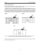
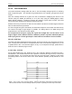
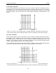
Table Of Contents
- 1 General Overview
- 2 Noggin Components
- 3 Noggin 100 Assembly
- 4 SmartCart Assembly
- 5 SmartTow Assembly
- 6 SmartHandle Assembly (Noggin 500 & 1000 only)
- 7 Rock Noggin Assembly (Noggin 500 & 1000 only)
- 8 Connecting GPS
- 9 Digital Video Logger (DVL)
- 10 Powering Up the System
- 11 Locate & Mark Mode
- 12 Survey & Map Mode
- 12.1 Survey & Map Menu
- 12.2 Data Acquisition
- 12.2.1 Replaying or Overwriting Data
- 12.2.2 Screen Overview
- 12.2.3 Position Information
- 12.2.4 Data Display
- 12.2.5 Section C - Menu
- 12.2.6 Gain
- 12.2.7 Collecting Data using the Odometer
- 12.2.8 Collecting Data in Free Run Mode
- 12.2.9 Collecting Data using the Trigger (or B) Button
- 12.2.10 Noggin Data Screens
- 12.2.11 Calib. (Calibration) Menu
- 12.2.12 Error Messages
- 12.3 Noggin Setup
- 12.4 Noggin File Management
- 12.5 Noggin Utilities
- 13 Troubleshooting
- 14 Care and Maintenance
- Appendix A Noggin Data file Format
- Appendix B Health & Safety Certification
- Appendix C GPR Emissions, Interference and Regulations
- Appendix D Instrument Interference
- Appendix E Safety Around Explosive Devices
- Appendix F Using the PXFER Cable and WinPXFER Software
- F1 Transferring Data to a PC using the PXFER Cable
- F1.1 Connecting the Digital Video Logger to a PC
- F1.2 PXFER Cable Types
- F1.3 Installing and Running the WinPXFER Program
- F1.4 Setting the DVL to the PXFER Cable Type
- F1.5 Transferring Noggin Data Buffer Files
- F1.6 Exporting Nogginplus Data
- F2 Transferring One or More Noggin PCX Files to an External PC using WinPXFER
- Appendix G GPR Glossaries

12-Survey & Map Mode Noggin
92
12.3.3 Line Parameters
The Line Parameters settings allow the user to view and modify settings specific to collecting
data as individual lines, namely, the starting position of the line and line direction.
12.3.3.1 Start Position
The Start Position is the position value at the very beginning of a line. This will usually be set to
zero (0.0). However, if the user wants a data file to start at a position other than zero, this value
can be edited.
12.3.3.2 Line Direction
The Line Direction setting specifies which direction that line will be collected, either Forward or
Reverse. Data are usually collected in a forward direction.
If data are collected in the Forward direction the position stepsize is positive, that is, the position
value of each data collection point increments positively. For example, for a Noggin 250 system,
if the Start Position is 10.0 and the Line Direction is Forward, the positions on the line will
increment 10.00, 10.05, 10.10, 10.15 ….
If data are collected in the Reverse direction the position stepsize is negative, that is, the position
value of each data collection point increments negatively. For example, for a Noggin 250 system,
if the Start Position is 10.0 and the Line Direction is Reverse, the positions on the line will
decrement 10.00, 9.95, 9.90, 9.85 ….