
User's Manual
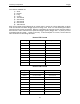
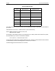
Table Of Contents
- 1 General Overview
- 2 Noggin Components
- 3 Noggin 100 Assembly
- 4 SmartCart Assembly
- 5 SmartTow Assembly
- 6 SmartHandle Assembly (Noggin 500 & 1000 only)
- 7 Rock Noggin Assembly (Noggin 500 & 1000 only)
- 8 Connecting GPS
- 9 Digital Video Logger (DVL)
- 10 Powering Up the System
- 11 Locate & Mark Mode
- 12 Survey & Map Mode
- 12.1 Survey & Map Menu
- 12.2 Data Acquisition
- 12.2.1 Replaying or Overwriting Data
- 12.2.2 Screen Overview
- 12.2.3 Position Information
- 12.2.4 Data Display
- 12.2.5 Section C - Menu
- 12.2.6 Gain
- 12.2.7 Collecting Data using the Odometer
- 12.2.8 Collecting Data in Free Run Mode
- 12.2.9 Collecting Data using the Trigger (or B) Button
- 12.2.10 Noggin Data Screens
- 12.2.11 Calib. (Calibration) Menu
- 12.2.12 Error Messages
- 12.3 Noggin Setup
- 12.4 Noggin File Management
- 12.5 Noggin Utilities
- 13 Troubleshooting
- 14 Care and Maintenance
- Appendix A Noggin Data file Format
- Appendix B Health & Safety Certification
- Appendix C GPR Emissions, Interference and Regulations
- Appendix D Instrument Interference
- Appendix E Safety Around Explosive Devices
- Appendix F Using the PXFER Cable and WinPXFER Software
- F1 Transferring Data to a PC using the PXFER Cable
- F1.1 Connecting the Digital Video Logger to a PC
- F1.2 PXFER Cable Types
- F1.3 Installing and Running the WinPXFER Program
- F1.4 Setting the DVL to the PXFER Cable Type
- F1.5 Transferring Noggin Data Buffer Files
- F1.6 Exporting Nogginplus Data
- F2 Transferring One or More Noggin PCX Files to an External PC using WinPXFER
- Appendix G GPR Glossaries

Noggin 12-Survey & Map Mode
91
For standard Smart Systems the Transfer Rate value must be set to 8.
The Transfer Rate value will only be decreased for systems with data cables longer than
standard lengths. Please contact Sensors & Software before changing the Transfer Rate on your
system.
12.3.2.7 Odometer Number
Noggin Smart Systems can take input from several different odometers.
It is very important that the user selects and calibrates the odometer appropriate for their
Smart System.
When Odometer Number is selected, the user is prompted to select the odometer that is being
used with the Smart System.
If a SmartCart System is being used, select one of the two SmartCart odometers (usually #1).
If a SmartHandle system is being used, select one of the two SmartHandle odometers (usually
#1).
If the system is being towed behind a vehicle and using the transmission odometer to trigger the
system, select one of the two Vehicle odometers (usually #1).
The odometers labelled Other are to be used in future configurations.
The number after the odometer is the current Odometer Calibration value for that odometer. To
calibrate the odometer, see Section 12.5.2: P.110.