
User's Manual
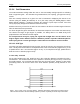
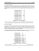
Table Of Contents
- 1 General Overview
- 2 Noggin Components
- 3 Noggin 100 Assembly
- 4 SmartCart Assembly
- 5 SmartTow Assembly
- 6 SmartHandle Assembly (Noggin 500 & 1000 only)
- 7 Rock Noggin Assembly (Noggin 500 & 1000 only)
- 8 Connecting GPS
- 9 Digital Video Logger (DVL)
- 10 Powering Up the System
- 11 Locate & Mark Mode
- 12 Survey & Map Mode
- 12.1 Survey & Map Menu
- 12.2 Data Acquisition
- 12.2.1 Replaying or Overwriting Data
- 12.2.2 Screen Overview
- 12.2.3 Position Information
- 12.2.4 Data Display
- 12.2.5 Section C - Menu
- 12.2.6 Gain
- 12.2.7 Collecting Data using the Odometer
- 12.2.8 Collecting Data in Free Run Mode
- 12.2.9 Collecting Data using the Trigger (or B) Button
- 12.2.10 Noggin Data Screens
- 12.2.11 Calib. (Calibration) Menu
- 12.2.12 Error Messages
- 12.3 Noggin Setup
- 12.4 Noggin File Management
- 12.5 Noggin Utilities
- 13 Troubleshooting
- 14 Care and Maintenance
- Appendix A Noggin Data file Format
- Appendix B Health & Safety Certification
- Appendix C GPR Emissions, Interference and Regulations
- Appendix D Instrument Interference
- Appendix E Safety Around Explosive Devices
- Appendix F Using the PXFER Cable and WinPXFER Software
- F1 Transferring Data to a PC using the PXFER Cable
- F1.1 Connecting the Digital Video Logger to a PC
- F1.2 PXFER Cable Types
- F1.3 Installing and Running the WinPXFER Program
- F1.4 Setting the DVL to the PXFER Cable Type
- F1.5 Transferring Noggin Data Buffer Files
- F1.6 Exporting Nogginplus Data
- F2 Transferring One or More Noggin PCX Files to an External PC using WinPXFER
- Appendix G GPR Glossaries

Noggin 12-Survey & Map Mode
89
12.3.2 Cart Parameters
The Cart Parameters settings allow the user to view and modify settings specific to the Smart
System. This includes the direction the Noggin will move to collect data, whether or not the
odometer is active and whether Auto Start is on or off.
12.3.2.1 Cart Direction
This setting determines whether data are collected as the Noggin is pushed forward or pulled in
reverse. The back up arrow (see Section 12.2.7: P.74) will work in the direction opposite to this
setting. The available options are:
1) Push (default)
2) Pull
12.3.2.2 Trigger Method
This setting determines the method used to trigger the Smart System to collect data at each data
collection point. The available options are:
1) Odometer
2) Free Run
3) Button
Trigger with Odometer: Selecting this option means that the Smart System will be triggered to
collect data using the input from the currently selected odometer (see Odometer Number below).
See Section 12.2.7: P.74 for more details about data acquisition with an odometer.
When collecting data with an odometer, data quality can be increased using the DynaQ stacking
option (Section 12.3.1.5 Stacks).
Free Run Operation: Selecting this option means that the Smart System runs continuously in
time, independent of any other triggering device (see Section 12.2.8: P.75). When continuous
operation is selected, two other menus appear to select the number of stacks and time delay
between data traces. These options allow the user to control the speed of the data acquisition.
The user can control the speed the Noggin collects data by increasing or decreasing the number
of stacks (for more details on Stacking, see Stacks on page 86). Increasing the number of Stacks
has the effect of slowing down the data collection speed of the Noggin system. Decreasing the
number of Stacks has the effect of speeding up the data collection speed of the Noggin system.
The second menu to appear prompts the user to input the time delay, in seconds, between each
data collection point. To run the system as quickly as possible, set this value to 0.0 seconds. For
a longer time delay, use the buttons to set the value. Note that any time delay longer than zero
(0.0) seconds causes the Smart System to emit a beeping sound to indicate data collection is
taking place.
The number of stacks and time delay should be set to values that, when combined with speed
the Noggin is moving at, provide an appropriate station interval. This may take a little
experimenting to determine the optimal values for stacks, time delay and the actual speed the
Noggin is moving at.
Trigger with Button: Selecting this means that the Smart System will be triggered to collect data
by pressing the trigger button (if the Smart System has a trigger button) or the B button on the
DVL (see Section 12.2.9: P.76).