
User's Manual
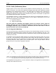
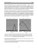
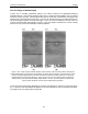
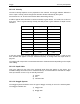
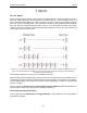
Table Of Contents
- 1 General Overview
- 2 Noggin Components
- 3 Noggin 100 Assembly
- 4 SmartCart Assembly
- 5 SmartTow Assembly
- 6 SmartHandle Assembly (Noggin 500 & 1000 only)
- 7 Rock Noggin Assembly (Noggin 500 & 1000 only)
- 8 Connecting GPS
- 9 Digital Video Logger (DVL)
- 10 Powering Up the System
- 11 Locate & Mark Mode
- 12 Survey & Map Mode
- 12.1 Survey & Map Menu
- 12.2 Data Acquisition
- 12.2.1 Replaying or Overwriting Data
- 12.2.2 Screen Overview
- 12.2.3 Position Information
- 12.2.4 Data Display
- 12.2.5 Section C - Menu
- 12.2.6 Gain
- 12.2.7 Collecting Data using the Odometer
- 12.2.8 Collecting Data in Free Run Mode
- 12.2.9 Collecting Data using the Trigger (or B) Button
- 12.2.10 Noggin Data Screens
- 12.2.11 Calib. (Calibration) Menu
- 12.2.12 Error Messages
- 12.3 Noggin Setup
- 12.4 Noggin File Management
- 12.5 Noggin Utilities
- 13 Troubleshooting
- 14 Care and Maintenance
- Appendix A Noggin Data file Format
- Appendix B Health & Safety Certification
- Appendix C GPR Emissions, Interference and Regulations
- Appendix D Instrument Interference
- Appendix E Safety Around Explosive Devices
- Appendix F Using the PXFER Cable and WinPXFER Software
- F1 Transferring Data to a PC using the PXFER Cable
- F1.1 Connecting the Digital Video Logger to a PC
- F1.2 PXFER Cable Types
- F1.3 Installing and Running the WinPXFER Program
- F1.4 Setting the DVL to the PXFER Cable Type
- F1.5 Transferring Noggin Data Buffer Files
- F1.6 Exporting Nogginplus Data
- F2 Transferring One or More Noggin PCX Files to an External PC using WinPXFER
- Appendix G GPR Glossaries

12-Survey & Map Mode Noggin
88
12.3.1.6 Linear Time Gain
As described in Section 12.2.6: P.73, the weak signals must be amplified or “gained” to see them
on the display. The Gain button described in Section 12.2.6: P.73 can be set to a value from 1 to
9 depending on the amount of gain required (1 is lowest gain, 9 is highest gain).
There is also a second level of gain available to the user and that is the Linear Gain setting. The
default Linear Gain setting of 2.0 is usually adequate for most ground conditions, however, if
advanced users find that they are surveying in areas where high Gain button settings are always
required to see data, it may be advantageous to increase the Linear Gain setting. Conversely, if
the user finds that low Gain button values work to see the data, it may be useful to decrease the
Linear Gain setting.
For the experienced user, the setting indicates the gain increases per nanosecond.
The Linear Gain setting can vary from 0.0 to 5.0 in steps of 0.5.
12.3.1.7 Position Units
This is the setting for the position units used by the odometer. The available options are:
1) metres (default)
2) feet