
User's Manual


8-Rock Noggin Configuration Assembly (Noggin 500 & 1000 only) Noggin
38
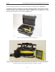
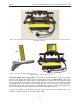
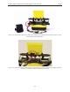
Figure: 8-4 The Rock Noggin system disassembled into its basic components and ready for assembly. More details
of each component are given in the figures below.
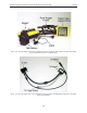
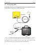
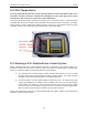
Figure: 8-5 The Rock Noggin cable. The 4 connections are for the Noggin, the Digital Video Logger (DVL), the trigger
button and the battery.