
User's Manual


4-Base Configuration Assembly Noggin
6
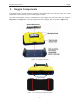
4 Base Configuration Assembly
The Base Noggin Configuration consists of the parts shown in Figure 4-1 (a Noggin 500 is
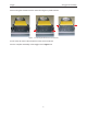
shown but any Noggin (100, 250, 500 or 1000) could be included). The assembled system is
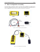
shown in Figure 4-2. Follow the directions below to assemble the configuration.
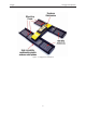
Figure: 4-1 Base Noggin 500 system components.
Figure: 4-2 Base Noggin system assembled.
Noggin
DVL
Belt Battery
Battery
Connection
DVL Connection
Cable
Noggin Connection