
Installation Guide

2 of 3
WPD
Dimmer Switch
PHASE DIMMING • 3-WAY • 120VAC
Acuity Brands | One Lithonia Way Conyers, GA 30012 Phone: 800.535.2465 www.acuitybrands.com © 2019 Acuity Brands Lighting, Inc. All rights reserved. Rev. 04/14/2020
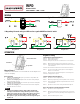
TYPICAL INSTALLATION
MULTI GANG INSTALLATION
Air Gap Switch
• WARNING: To avoid fire, shock, or death. High Voltage - Turn off power at circuit
breaker or fuse and test that power is off before wiring.
• CAUTION: To reduce the risk of overheating and possible damage to other equip-
ment, DO NOT install to control a receptacle, a motor-operated appliance, a fluores-
cent lighting fixture, or a transformer supplied appliance.
• Remove wall plate and existing switch mounting screws.
• Carefully remove the existing switch from the switch box.
• Disconnect the wiring from the existing switch.
• Connect the dimmer switch as shown in the wiring diagram: Black lead to hot wire,
white lead to neutral wire, red lead to load wire, green lead to ground wire.
• Check connections to be sure they are tight, and no bare conductors are exposed.
• Insert the WPD dimmer switch into the standard outlet box carefully.
• Make sure the WPD dimmer switch supplied screws in designated location.
• Attach the wall plate.
• Restore power at the circuit breaker and test the system.
For further troubleshooting guidance, please contact the Controls Technical Support Team
1(800)-535-2465
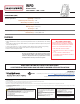
The Sensor Switch WPD is an economical commercial/residential grade forward phase paddle dimmer for LED, CFT, Incandescent, and Dimmable LED
compatible loads. Easy configuration is a key feature of this device, allowing the user or installer to effortlessly develop energy saving illumination
strategies by setting high and low brightness levels or returning to its default state when desired. Its elegant design does not compromise function. This
UL 1472 Listed and NEMA SSL 7A solution accepts line 120VAC voltage from a single device, including a sliding Air-Gap switch to disconnect power while
replacing bulbs. The WPD also works as works with a mechanical switch for 3-Way wiring.
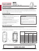
When installing more than one control in a multi-gang wall box, it may be necessary to remove side tabs before installing (see image below). Bending tabs
back and forth using pliers will easily break tabs. Tab removal will reduce maximum load capacity.
When using the Dimmer to control LED/CFL lights in conjunction with another Dimmer to control Incandescent /Halogen lights follow this Derating Chart
(below right) for Maximum capacity on EACH device.
During normal operation, there is a small amount of power passing
through the switch to the load even when the dimmer switch is
turned off. The WPD has an air gap switch on the lower right side to
completely disconnect load power.
Slide the air gap switch to left to disconnect the power while
replacing light bulbs and slide it to right for normal operation.
The air gap switch must be in one of two positions to function as
intended.
WPD BASIC OVERVIEW
Tabs Removed for Multi-gang Installation
If you are using ONLY LED/CFL bulbs on ALL Dimmers, DO NOT USE this
Derating Chart. Dimmable LED/CFL load capacity is 150W in all cases.
Combined Wattage
of ALL LED/CFL bulbs
on 1 dimmer is:
Then the Maximum COMBINED Wattage for the
Incandescent/Halogen bulbs on EACH attached dimmer:
If NO Tabs are
removed, then Max
Wattage is:
If 1 side of Tabs are
removed, then Max
Wattage is:
If 2 sides of Tabs are
removed, then Max
Wattage is:
0W 600W 500W 400W
1-25W 500W 400W 300W
26-50W 400W 300W 200W
51-75W 300W 200W 100W
76-100W 200W 100W 50W
101-125W 100W 50W 0W
126-150W 0W 0W 0W