
Installation Guide

Acuity Brands | One Lithonia Way Conyers, GA 30012 Phone: 800.535.2465 www.acuitybrands.com/sensorswitch
© 2014-2019 Acuity Brands Lighting, Inc. All rights reserved. Rev. 05/02/19
CM Family
3 of 4
STANDARD WIRING
RED - Power Input (12-24 VAC/VDC)
BLACK - Common
WHITE - Occupancy State (high VDC for occupied)
PHOTOCELL / DIMMING OPTIONS (D, P, ADC)
BLUE - Direct output to power pack for providing photocell control and/or
secondary dim time out. Output is high VDC with occupancy & low light. Output
also held high during secondary dim time out. For multi-level control, use two
power packs and connect White wire to primary load and Blue to daylight load.
VIOLET w/ WHITE STRIPE - Connect to 0-10 VDC control wire (typically Violet) from
0-10 VDC dimmable ballast
GRAY from Ballast - Connect to sensor Black wire
RELAY OPTION (R)
GRAY / BROWN - Connected during occupied state
VIOLET / BROWN - Connected during unoccupied state
Note: Relay is energized during unoccupied state
• Mount sensor directly to a ceiling tile or a metallic grid (two self-tapping
screws provided).
• Sensor’s mounting holes also align with 3.5” octagon or single gang handy
box (screws not provided).
• Sensor will detect motions crossing segments more effectively than motions
parallel to beams.
• For optimal detection, position sensor such that segments are crossed upon
entrance and unable to view outside the space.
• PDT models: For maximum Microphonics sensitivity avoid locating sensor
near HVAC air diffusers
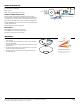
WIRING (DO NOT WIRE HOT)
INSTALLATION
R - RELAY OPTION
BLK - 120 V
ORN - 277 V
D, P, ADC - PHOTOCELL / DIMMING OPTIONS
PP20
PUSH BUTTON
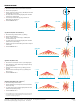
*At 9ft Mtg.
A: When walking across beam, detection will
occur at approximately 28 feet. (8.53 m)
B: When walking into beam, detection will
occur at approximately 24 feet. (7.32 m)