
User's Manual

Sensor Maestros
P a g e | 5 Revised: Novermber 30, 2022
PCB Trace Antenna
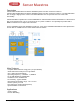
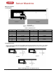
1. Dimensions
Figure 1. IFA
Dimensions
Table 1. IFA
Dimensions
H1
5.70 mm
W2
0.46 mm
H2
0.74 mm
L1
25.58 mm
H3
1.29 mm
L2
16.40 mm
H4
2.21 mm
L3
2.18 mm
H5
0.66 mm
L4
4.80 mm
H6
1.21 mm
L5
1.00 mm
H7
0.80 mm
L6
1.00 mm
H8
1.80 mm
L7
3.20 mm
H9
0.61 mm
L8
0.45 mm
W1
1.21 mm
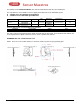
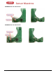
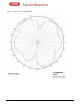
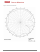
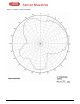
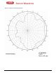
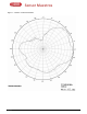
2. Radiation Pattern
Figure 2 shows how to relate all of the radiation patterns to the orientation of the antenna. The radiation
patterns were measured with the RADMEDIA-BLE-T21/RADMEDIA-BLE-T22 device programmed to
0-dBm output power.
Figure 2. Relating Antenna to Radiation
Patterns