
Operating instructions


9
8. To save the settings, press the Zero+Span buttons until the
SelInc message appears.
• CHANGE UNITS
1. Access the menu by pressing the Zero+Span buttons.
2. Move to next menu by pressing the Zero button until the
1 TRIM message appears.
3
. Moving thru the sub directory press the Span button until
the 2 SETUP message appears.
4. Press the Span button to access 21 UNIT, press Span
again to access Change Unit.
5. Save the values by pressing the Span button when the
desired value is displayed on the LCD.
• CHANGE UPPER RANGE VALUE
1. Access the menu by pressing the Zero+Span buttons.
2. Move to next menu by pressing the Zero button until the
1 TRIM message appears.
3. Press the Span button until the 2 SETUP message
appears.
4. Press the Span button until the 21 Unit message appears.
5. Press the Zero button until the 22 U-RNG message
appears.
6. Press the Span button until the Zero Adjustment message
appears.
• CHANGE LOWER RANGE VALUE
1. Access the menu by pressing the Zero+Span buttons.
2. Move to next menu by pressing the Zero button until the
1 TRIM message appears.
3. Press the Span button until the 2 SETUP message appears.
4. Press the Span button until the 21 Unit message appears.
5. Press the Zero button until the 22 U-RNG message
appears.
6. Press the Zero button until the 23 L-RNG message
appears.
7. Press the Span button until the Change Lower Range
Value message appears.
• CHANGE LCD MODE (Cyclic or Fixed Display)
1. Enter programming menu by pushing both (ZERO+SPAN)
button together for 5 seconds. Release buttons when LCD
displays Menu and display will automatically change to
“1 TRIM” confirming access into programming menu.
2. Push (ZERO) button when “1 TRIM” message appears on
LCD. Release button when display changes to “2 SETUP”.
3. Push (Zero) button and release when display changes to
“3 LCD”.
4. To move into sub directory push (Span) button after
“3 LCD” message appears on display. Release button
when 31 LCDMD message is displayed.
5. To enter this sub-menu, push (Span) button and release
when display changes to 311. Bottom line of display will
show current Mode setting (e.g. NOR-RO, NOR-PV. etc).
6. Push (Zero) button to cycle through available mode
options and select desired LCD rotation mode. Options are
NOR-RO (rotate all PV, %, mA), NOR-PV (fixed PV),
NOR-% (fixed %), NOR-mA fixed, ENG-RO, ENG-PV,
ENG-% or ENG-mA
7. Push (Span) to save changes and EXIT programming
mode.
• DECIMAL PLACE
1. Access the menu by pressing the Zero+Span buttons.
2. Move to next menu by pressing the Zero button until the
1 TRIM message appears.
3. Press the Span button until the 2 SETUP message appears.
4. Press the Span button until the 3 LCD message appears.
5. Press the Span button until the 31 DEC-PL message
appears.
6. Press the Span button until the Decimal Place message
appears. The decimal place will appear on the second line
of the LCD as follows:
7. The first line on the LCD will display 0.0.
8. The Decimal Place can be changed by pressing the Zero
button. Save the setting by pressing the Span button after
the decimal place has been selected.
9. The set value will display the PV value and Engineering
value.
10. The LCD will display LCD_OV and the saved Unit when the
pressure is over or under a set value.
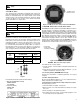
3.8 Commissioning on the Bench with HHT:
The 3100 Pressure Transmitter can be commissioned using an
HHT before or after installation.
Connect an HHT (HART
®
HANDHELD Communicator) across the
COMM pins for HART
®
communication. The TEST pin connec-
tions can be used for connecting a multimeter to measure the out-
put current directly from the transmitter. Since the 3100 is a two
wire loop powered transmitter, it requires an external loop power
supply (11.9V to 45VDC) to enable HART
®
communication. Any
HART
®
communication via HHT (or PC based configurator)
requires a minimum 250 - 550 (max) ohm loop resistance.
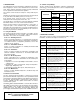
DISPLAY EXPLANATION
MAX.
VALUE
AUTO Target value will be displayed automatically 99999
5-0 No decimal place 99999
4-1 Display one decimal place 9999.9
3-2 Display two decimal places 999.99
2-3 Display three decimal places 99.999
1-4 Display four decimal places 9.9999
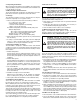
Figure 6: Connecting the Transmitter to HHT
POWER/SIGNAL CONNECTIONS
1. HHT (HART Communicator) or PC Configurator may be connected at any ter-
minal point in the signal loop.
2. HART Communication requires a loop resistance between 250 and 550 ohm
(24 VDC).
3. Transmitters operate on 11.9 to 45.0 VDC terminal voltage.
Applied Power:
• 11.9 - 45.0 VDC for general operation
• 17.4 - 45.0 VDC for HART Communication