
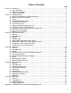
Operating instructions


minal. Be sure to connect the grounding lead of the dielectric
strength tester to the ground terminal.
3. Set the current limit on the dielectric strength tester to 10 mA,
then turn on the power and gradually increase the tester volt-
age from ‘0’ to the specified voltage.
4. When the specified voltage is reached, hold it for one minute.
5. After completing this test, slowly decrease the voltage to avoid
any voltage surges.
2
.10 Explosion-Proof Rating:
2.10.1 FM Certification:
HAZARDOUS LOCATION ELECTRICAL EQUIPMENT
• Equipment Rating: Explosion-Proof for use in Class I,
Division 1, Groups A, B, C and D
• Dust- Ignition-Proof for Class II/III, Division 1, Groups E, F
and G
• Nonincensive for use in Class I, Division 2, Groups A, B, C
and D
• Suitable for use in Class II, Division 2, Groups E, F and G
and Suitable for Class III, Division 1
• Hazardous (classified) location, indoor and outdoor (NEMA
Type 4X/IP67)
2.10.2 DEKRA/ATEX Certification:
• ATEX Certification number: DEKRA 11ATEX0192X
• CE 0344 II 2 G
Model 3100 for Potentially Explosive Atmosphere
• d IIC T6...T4
• Operating Temperature: -20°C ≤ T
amb ≤ +60°C
• T6 for process ≤ 85°C
• T5 for process ≤ 100°C
• T4 for process ≤ 130°C
Electrical Data
• Supply Voltage: 42 VDC Max
• Output Signal: 4 to 20 mA + HART
Electrical Connection
• 2 x
1
⁄2-14 NPT Female
3100 ATEX Certification Standards
• EN 60079-0: 2006
• EN 60079-1: 2007
Installation
1. All wiring shall comply with local installation requirement.
2. The cable glands and blanking elements shall be of a certified
flameproof type, suitable for the condition of use and correctly
installed. Also those devices should be endured at the 130°C.
3. Housing Ground must be followed to “local electrical codes”.
The most efficient ground procedure is to connect directly to
the earth as least impedance.
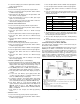
4. How to install Housing Ground:
• Internal Ground Connection – Internal ground connection
screw is located in terminal in housing. The screw can be
identified as ground sign.
• External Ground Assembly – This is located in the right side
of housing and identified by ground sign (grounding with a
cable lug).
5
. When use tubing, stopping boxes must be connected with the
wall of housing directly.
6. Tubing is installed a minimum of 5 threads.
7. Sensor is to be threaded a minimum of 7 threads and prevent-
ed from turning by tightening the housing rotation set screw.
8. Do not disassemble flameproof joints but in an unavoidable
case to disassemble it or need the specification of flameproof
joints, contact the manufacturer before doing.
Operation
Take care not to generate mechanical spark when access to the
instrument and peripheral devices in hazardous location.
Maintenance and Repair
The instrument modification or parts replacement by other than
authorized representative of Taco, Inc. is prohibited and will void
KEMA/ATEX explosion-proof/flame-proof.
2.11 EMC Conformity Standards:
• EMI (Emission): EN55011
• EMS (Immunity): EN50082-2
Taco, Inc. recommends customer use metal conduit wiring or
twisted pair shield cable for signal wiring to conform with EMC
regulation when installing the Taco 3100 transmitters.
3. TRANSMITTER FUNCTIONS:
3.1 Overview:
This section contains information on operating the Model 3100.
Tasks that should be performed on the bench prior to installation
are explained in this section.
3.2 Safety Messages:
Procedures and instructions in this section may require special
precautions to ensure the safety of the personnel performing the
operations. Potential safety issues are indicated by a warning
symbol ( ). Refer to the following safety messages before per-
forming an operation preceded by this symbol.
3.3 Warning:
Do not remove the transmitter covers in explosion environments
when the circuit is powered. Transmitter covers must be fully
engaged to meet explosion-proof requirements.
6
NOTICE
NOTICE
NOTICE
NOTICE
NOTICE
NOTICE
NOTICE
WARNING: Do not open when an explosive atmos-
phere may be present.
DANGER: Explosion can result in death or serious
injury.