
Operating instructions


13
5.2.1 Warning:
5.2.2 Current to Passive Mode Configuration:
For multi-drop mode the current output must be configured as pas-
sive mode. Please disregard any other messages shown on HHT.
5.3 Configuration Data Review:
Before operating the transmitter make sure the configuration data
on the nameplate matches the application.
5.4 Configuration Verification:
Before the transmitter is ready for service, the configuration must be
checked to confirm the settings are configured for the application.
5.4.1 Process Variable:
There are two process variables in the 3100 Smart Pressure
Transmitter. The primary variable and temperature compensated SV
(Second Variable), the PV value outputs the 4~20mA analog value.
5.5 Basic Setup:
The correlation variable must be configured before operating the
transmitter.
5.5.1 Select Sensor Range:
The pressure range must be selected when ordering the pressure
transmitter.
5.5.2 Set Output Units:
Select from the following engineering units:
Volumetric Flow Unit -
CubicFeet/min, Gallons/min, Liters/min,
ImperialGallons/min, CubicMeter/hr, Ft/s, meters/s,
Gallons/s, mGallons/day, Liters/s, mLiters/day, CubicFeet/s,
CubicMeter/s, CubicMeter/day, ImperialGallons/hr,
ImperialGallons/day, NormalCubicMeter/hr, NormalLiter/hr,
StandardCubicFeet/min, CubicFeet/hr, CubicFeet/day,
CubicMeters/min, Barrels/s, Barrels/min, Barrels/hr,
Barrels/day, Gallons/hr, ImperialGallons/s, Liters/hr,
Gallons/day
Mass Flow -
Grams/s, Grams/min, Grams/hr, Kilograms/s,
Kilograms/min, Kilograms/hr, Kilograms/day,
MetricTons/min, MetricTons/hr, MetricTons/day, Pounds/s,
Pounds/min, Pounds/hr, Pounds/day, ShortTons/min,
ShortTons/hr, ShortTons/day, LongTons/hr, LongTons/day
Pressure -
kPa, mmH2O, InH2O, InHg, FtH2O, mmHg, psi, bar, mbar,
g/cm
2
, Kg/cm
2
, Pascals, MPa, torr, ATM
Miscellaneous -
%
Time -
Min, sec, hr, days
Mass -
Grams, kilograms, metric tons, pounds, short tons, long tons,
ounce
Volume -
Gallons, liters, imperial gallons, cubic meters, barrels,
bushels, cubic yards, cubic feet, cubic inches, bbl liq, normal
cubic meter, normal liter, standard cubic feet, hectoliters
5.5.3 4-20mA Configuration:
Set the Zero and Span for the 4~20mA analog output.
5.6 Detailed Setup:
5.6.1 Set Fail Mode:
When the sensor or microprocessor is not operating properly, the
transmitter will output 3.75mA or 21.75mA based on the Fail
Mode setting.
5.6.2 Set Dampening Time:
The Dampening Seconds value changes the response time of the
t
ransmitter to smooth out variations caused by rapid process
changes. Determine the appropriate dampening setting based on
the required response time, signal stability, and other require-
ments of your system.
The Dampening Seconds can be set from 0-60 seconds; the
default dampening value is 1.0 second.
5.7 Configuration of Information Variable:
5.7.1 Set Tag:
Tags are an easy way to classify transmitters in multi transmitter
application. Tags can use 8 words/numbers.
5.7.2 Set Messages:
When using several transmitters, the user can define each transmit-
ter by using 32 words/numbers. This message is saved in EEPROM.
5.8 Diagnostics and Service:
5.8.1 Loop Test:
The Loop Test verifies the output of the transmitter, the integrity of
the loop, and the operations of any recorders or similar devices
installed in the loop. The following procedures are required for a
loop test.
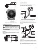
• Connect a reference meter to the transmitter.
• Select the Loop Test on the HHT and operate the Loop Test.
• Select current output (4mA/20mA/etc.)
• If the readings match, then the transmitter and the loop are
configured and functioning properly. If the readings do not
match, then you may have the current meter attached to the
wrong loop, there may be a fault in the wiring, the transmitter
may require an output trim, or the current meter may be mal-
functioning.
5.9 Calibration:
The scale is implemented by calibrating the transmitter. Trim func-
tion has several calibration functions. Smart transmitters operate
differently than analog transmitter. A smart transmitter uses a
microprocessor that contains information about the sensor's spe-
cific characteristics in response to pressure and temperature for
calculating the process variable. 4-20mA configuration sets the
D
ANGER: Explosion can result in death or serious
injury. Do not remove the transmitter covers in
e
xplosion-proof environments when the circuit is
powered. Both transmitter covers must be fully
e
ngaged to meet explosion-proof requirements.
DANGER: Electrical shock can result in serious
injury. When installing transmitters in close proxim-
ity of high voltage sources (near power lines) the
transmitter leads can be subject to high voltages.
Avoid contact with the leads and terminals.
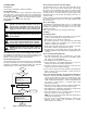
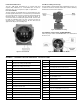
Figure 17