
Operating instructions


10
4. INSTALLATION:
4.1 Overview:
The information in Chapter 4 explains installation.
4.2 Safety Messages:
Procedures and instructions in this chapter may require special
safety measures to ensure the safety of the personnel performing
the operation. Potential installation safety issues are indicated by
a safety alert symbol ( ). Refer to the following safety messages
before installing the 3100 pressure transmitter.
4.3 Warning:
4.4 Commissioning on the Bench with Hand-Held Terminal:
The 3100 Pressure Transmitter can be commissioned before and
after installation. Commissioning is easier if the transmitter is con-
figured on a bench with an HHT before installation.
4.5 General Considerations:
The transmitter can be mounted near the process to minimize pip-
ing. Keep in mind that easy access is required for personnel, field
calibration, and installation. Install the transmitter in an area with
minimal vibration, shock, and temperature fluctuations.
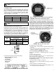
4.6 Electrical Considerations (Power Supply):
The transmitter housing is composed of two parts. One side is
electronics, and the other side is terminal block. The terminal
block side is the transmitter’s front side and is labeled “Field
Terminal” on the housing. The terminal block can be accessed by
removing the front cover. When wiring the power supply to the
transmitter make sure the positive and negative wires are con-
nected correctly.
A HHT configurator can be connected directly across the (COMM)
pin terminal located just below the power supply (PWR) terminal
block connections.
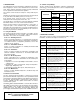
4.6.1 Power Supply:
T
he 3100 Pressure Transmitter requires an 11.9 – 45 VDC power
supply. A 250 ~ 550Ω (24 VDC) loop resistance is recommended
f
or HART
®
c
ommunication. Loop resistance is the sum of the
resistance in the loop.
Max. Loop Resistance [Ω] = (E-11.9) [vdc] / 0.022 [mA]
4.7 Wiring:
4.7.1 Wiring Caution:
1. Install the signal cables away from potential sources of electri-
cal noise such as transformers, electrical motors, etc.
2. Before wiring, remove electrical conduit cap.
3. All screwed connections on the housing must be sealed with
waterproof sealant. We recommend use of silicone based
sealants to minimize post-hardening.
4. Avoid running DC signal and AC power cables in the same
ducts/cable conduits to avoid signal noise issues.
5. All explosion-proof transmitters must meet the wiring and
installation requirements specified within the applicable electri-
cal codes.
4.7.2 Selecting the Wiring Materials:
1. Use 600V shielded PVC wire or standard wire of the same
class. (To ensure proper communication use 24 AWG or larger
wire, and do not exceed 5000 feet)
2. Use shielded wire in areas with electrical noise.
3. In areas with high or low ambient temperatures, use wire or
cable that is rated for the extreme temperatures.
4. If the wire or cable is going to be used in oil, solvent, toxic gas
or liquid, make sure it is rated accordingly.
5. Process wire or cable must not be soldered to the terminal lug.
Spade connectors are recommended to connect the process
wires to the transmitter.
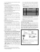
4.7.3 Connecting External Wires to Transmitter Terminal Box:
1. Open the cover indicated "FIELD TERMINAL". Do not open the
cover if the transmitter is located in an explosion-proof area
and powered. Connect the power supply to the terminal indi-
cated "+PWR"(left terminal) and "-" in the central terminal. Do
not connect "+" power supply to "+" terminal "TEST". It will
damage the test diode.
2. Seal and close the conduit connection to prevent humidity and
explosion-proof atmosphere from entering the housing.
3. Transmitter power is supplied by signal wire. Do not install near
high voltage wires or high voltage equipment.
4. Close the transmitter cover. To meet the explosion-proof rat-
ings make sure the covers are fully engaged.
NOTE: Do not power the transmitter with high voltage (AC). It
can damage the transmitter.
5. You must connect a 250~550 Ohm Resistor in Current Loop
(between Power Supply and Transmitter) for HART
®
Communication. See Figure 8.
WARNING: Process leaks can cause death or
serious injury. Install and tighten before applying
pressure. If you don’t, it can cause process leaks.
WARNING: Electrical shock can result in serious
injury. Only qualified personnel can wire the pres-
sure transmitter.
D
ANGER: Explosion can result in death or serious
injury. Do not remove the transmitter covers in an
e
xplosion-proof environment when the circuit is
powered. Both transmitter covers must be fully
engaged to meet the explosion-proof requirements.
DANGER: Electrical shock can result in death or
serious injury. Avoid contact with the leads and
terminals.
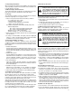
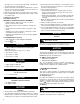
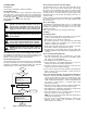
DO YOU WANT
START
BASIC SETUP
A) UNIT SETUP
B) RANGE SETUP
C) DAMPENING SETUP
D) TRANSMITTER FUNCTION SETUP
NO
YES
DO YOU
SATISFY SPEC
VERIFY
A) PRESSURE SUPPORT
MAINTENANCE
END
FIELD INSTALL
A) JUMPER/SWITCH SETUP
B) TRANSMITTER TAKES UP
C) TRANSMITTER LEADS
D) TRANSMITTER FOR POWER SUPPLY
Figure 7: Installation Flow Chart