
User Manual


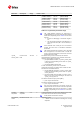
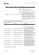


Table Of Contents
- Preface
- Contents
- 1 AT command settings
- 2 General operation
- 3 IPC - Inter Processor Communication
- 4 General
- 4.1 Manufacturer identification +CGMI
- 4.2 Manufacturer identification +GMI
- 4.3 Model identification +CGMM
- 4.4 Model identification +GMM
- 4.5 Firmware version identification +CGMR
- 4.6 Firmware version identification +GMR
- 4.7 Request product serial number identification +CGSN
- 4.8 IMEI identification +GSN
- 4.9 Identification information I
- 4.10 TE character set configuration +CSCS
- 4.11 International mobile subscriber identification +CIMI
- 4.12 Card identification +CCID
- 4.13 Repeat last command A/
- 5 Mobile equipment control and status
- 5.1 Phone activity status +CPAS
- 5.2 Module switch off +CPWROFF
- 5.3 Set module functionality +CFUN
- 5.4 Indicator control +CIND
- 5.5 Configuration of indicator control +UCIND
- 5.6 Mobile termination event reporting +CMER
- 5.7 Clock +CCLK
- 5.8 Set greeting text +CSGT
- 5.9 Automatic time zone update +CTZU
- 5.10 Report mobile termination error +CMEE
- 6 Call control
- 7 Network service
- 7.1 Network parameters definition
- 7.2 Subscriber number +CNUM
- 7.3 Signal quality +CSQ
- 7.4 Extended signal quality +CESQ
- 7.5 Operator selection +COPS
- 7.6 Radio Access Technology (RAT) selection +URAT
- 7.7 Network registration status +CREG
- 7.8 Network selection control +PACSP
- 7.9 Channel and network environment description +UCGED
- 7.10 Edit Verizon wireless APN table +VZWAPNE
- 7.11 Read RSRP values +VZWRSRP
- 7.12 Read RSRQ values +VZWRSRQ
- 7.13 Signalling connection status +CSCON
- 7.14 eDRX setting +CEDRXS
- 7.15 eDRX read dynamic parameters +CEDRXRDP
- 7.16 Set MNO profile +UMNOPROF
- 7.17 Band selection bitmask +UBANDMASK
- 7.18 Device service domain configuration +USVCDOMAIN
- 7.19 CIoT optimization configuration +CCIOTOPT
- 7.20 NB-IoT band scan tuning +UDCONF=77
- 8 Device lock
- 9 Short Messages Service
- 9.1 Introduction
- 9.2 Select message service +CSMS
- 9.3 Preferred message storage +CPMS
- 9.4 Preferred message format +CMGF
- 9.5 Save settings +CSAS
- 9.6 Restore settings +CRES
- 9.7 Show text mode parameters +CSDH
- 9.8 New message indication +CNMI
- 9.9 Read message +CMGR
- 9.10 New message acknowledgement to MT +CNMA
- 9.11 List message +CMGL
- 9.12 Send message +CMGS
- 9.13 Write message to memory +CMGW
- 9.14 Send message from storage +CMSS
- 9.15 Set text mode parameters +CSMP
- 9.16 Delete message +CMGD
- 9.17 Service center address +CSCA
- 9.18 Read concatenated message +UCMGR
- 9.19 List concatenated message +UCMGL
- 9.20 Send concatenated message +UCMGS
- 9.21 Write concatenated message to memory +UCMGW
- 9.22 More messages to send +CMMS
- 9.23 Sending of originating data via the control plane +CSODCP
- 9.24 Terminating data reporting via control plane +CRTDCP
- 10 V24 control and V25ter
- 10.1 Introduction
- 10.2 Circuit 109 behavior &C
- 10.3 Circuit 108/2 behavior &D
- 10.4 DSR override &S
- 10.5 DTE-DCE character framing +ICF
- 10.6 DTE-DCE local flow control +IFC
- 10.7 Set flow control \Q
- 10.8 UART data rate configuration +IPR
- 10.9 Return to on-line data state O
- 10.10 Escape character S2
- 10.11 Command line termination character S3
- 10.12 Response formatting character S4
- 10.13 Command line editing character S5
- 10.14 Pause before blind dialling S6
- 10.15 Connection completion timeout S7
- 10.16 Command dial modifier time S8
- 10.17 Automatic disconnect delay S10
- 10.18 Escape prompt delay (EPD) S12
- 10.19 Command echo E
- 10.20 Result code suppression Q
- 10.21 DCE response format V
- 10.22 Result code selection and call progress monitoring control X
- 10.23 Reset to default configuration Z
- 10.24 Set to factory defined configuration &F
- 10.25 Display current configuration &V
- 11 SIM management
- 12 SIM toolkit
- 13 Packet switched data services
- 13.1 PDP contexts and parameter definition
- 13.2 PPP LCP handshake behaviour
- 13.3 Printing IP address format +CGPIAF
- 13.4 PDP context definition +CGDCONT
- 13.5 Packet switched data configuration +UPSD
- 13.6 GPRS attach or detach +CGATT
- 13.7 PDP context activate or deactivate +CGACT
- 13.8 Enter PPP state/GPRS dial-up D*
- 13.9 Show PDP address +CGPADDR
- 13.10 Packet switched event reporting +CGEREP
- 13.11 GPRS network registration status +CGREG
- 13.12 UE modes of operation for EPS +CEMODE
- 13.13 EPS network registration status +CEREG
- 13.14 Delete non-active PDP contexts +CGDEL
- 13.15 Configure the authentication parameters of a PDP/EPS bearer +UAUTHREQ
- 13.16 PDP context read dynamic parameters +CGCONTRDP
- 13.17 Initial PDP context activation +CIPCA
- 13.18 PDP IP configuration when roaming +UDCONF=75
- 13.19 Disable data when roaming +UDCONF=76
- 14 System features
- 14.1 Firmware installation +UFWINSTALL
- 14.2 Firmware update Over AT (FOAT) +UFWUPD
- 14.3 Antenna detection +UANTR
- 14.4 End user test +UTEST
- 14.5 Internal temperature monitor +UTEMP
- 14.6 Back up the file system +UBKUPDATA
- 14.7 Cancel FOTA download +UFOTA
- 14.8 Sets FOTA status URCs +UFOTASTAT
- 14.9 uFOTA configuration +UFOTACONF
- 14.10 Last gasp configuration +ULGASP
- 14.11 RING line configuration +URINGCFG
- 15 Power management
- 16 GPIO
- 16.1 Introduction
- 16.1.1 GPIO functions
- 16.1.2 GPIO mapping
- 16.1.3 Network status indication
- 16.1.3.1 No service (no network coverage or not registered)
- 16.1.3.2 Registered home network 2G
- 16.1.3.3 Registered home network 3G
- 16.1.3.4 Registered home network NB1 / NB2
- 16.1.3.5 Registered roaming 2G
- 16.1.3.6 Registered roaming 3G
- 16.1.3.7 Registered roaming NB1 / NB2
- 16.1.3.8 Data transmission
- 16.1.3.9 Data transmission roaming
- 16.1.4 Module status indication
- 16.1.5 Module operating mode indication
- 16.2 GPIO select configuration command +UGPIOC
- 16.3 GPIO read command +UGPIOR
- 16.4 GPIO set command +UGPIOW
- 16.1 Introduction
- 17 File System
- 18 DNS
- 19 Internet protocol transport layer
- 19.1 Introduction
- 19.2 IPv4/IPv6 addressing
- 19.3 Create Socket +USOCR
- 19.4 SSL/TLS/DTLS mode configuration on TCP/UDP socket +USOSEC
- 19.5 Set socket option +USOSO
- 19.6 Get Socket Option +USOGO
- 19.7 Close Socket +USOCL
- 19.8 Get Socket Error +USOER
- 19.9 Connect Socket +USOCO
- 19.10 Write socket data +USOWR
- 19.11 SendTo command (UDP only) +USOST
- 19.12 Read Socket Data +USORD
- 19.13 Receive From command (UDP only) +USORF
- 19.14 Set Listening Socket +USOLI
- 19.15 HEX mode configuration +UDCONF=1
- 19.16 Set socket in Direct Link mode +USODL
- 19.17 UDP Direct Link Packet Size configuration +UDCONF=2
- 19.18 UDP Direct Link Sending timer configuration +UDCONF=3
- 19.19 Timer Trigger configuration for Direct Link +UDCONF=5
- 19.20 Data Length Trigger configuration for Direct Link +UDCONF=6
- 19.21 Character trigger configuration for Direct Link +UDCONF=7
- 19.22 Direct Link disconnect DSR line handling +UDCONF=10
- 19.23 Socket control +USOCTL
- 19.24 Configure Dormant Close Socket Behavior +USOCLCFG
- 20 Device and data security
- 20.1 Introduction
- 20.2 Device security
- 20.3 Data security
- 20.3.1 Introduction
- 20.3.1.1 SSL/TLS/DTLS
- 20.3.1.2 SARA-R410M-63B / SARA-R410M-73B / SARA-R410M-83B Local encryption and decryption
- 20.3.1.3 SARA-R410M-63B / SARA-R410M-73B / SARA-R410M-83B Pre-Shared Keys (PSK) provisioning
- 20.3.1.4 SARA-R410M-63B / SARA-R410M-73B / SARA-R410M-83B End-to-end data encryption and decryption
- 20.3.2 SSL/TLS certificates and private keys manager +USECMNG
- 20.3.3 SSL/TLS/DTLS security layer profile manager +USECPRF
- 20.3.4 AT+USECMNG command example
- 20.3.5 Notes
- 20.3.6 Local encryption from AT interface +USECDATAENC
- 20.3.7 Local decryption from AT interface +USECDATADEC
- 20.3.8 Local encryption from a file +USECFILEENC
- 20.3.9 Local decryption from a file +USECFILEDEC
- 20.3.10 Pre-Shared Key (PSK) generation +USECPSK
- 20.3.11 End to end encryption from AT interface +USECE2EDATAENC
- 20.3.12 End to end encryption from a file +USECE2EFILEENC
- 20.3.1 Introduction
- 21 FTP
- 22 HTTP
- 23 Positioning
- 23.1 NMEA
- 23.2 AssistNow services
- 23.3 GNSS
- 23.3.1 GNSS power management +UGPS
- 23.3.2 Assisted GNSS unsolicited indication +UGIND
- 23.3.3 GNSS profile configuration +UGPRF
- 23.3.4 Aiding server configuration +UGSRV
- 23.3.5 GNSS aiding request command +UGAOS
- 23.3.6 Send of UBX string +UGUBX
- 23.3.7 GNSS indications timer +UGTMR
- 23.3.8 Get GNSS time and date +UGZDA
- 23.3.9 Get GNSS fix data +UGGGA
- 23.3.10 Get geographic position +UGGLL
- 23.3.11 Get number of GNSS satellites in view +UGGSV
- 23.3.12 Get recommended minimum GNSS data +UGRMC
- 23.3.13 Get course over ground and ground speed +UGVTG
- 23.3.14 Get satellite information +UGGSA
- 23.4 CellLocate and hybrid positioning
- 24 I2C
- 25 MQTT
- 26 Lightweight M2M
- 26.1 LwM2M Objects management
- 26.1.1 Introduction
- 26.1.2 Load LwM2M object definition +ULWM2MADD
- 26.1.3 Remove LwM2M object definition +ULWM2MREMOVE
- 26.1.4 List available LwM2M objects +ULWM2MLIST
- 26.1.5 Create new instance of LwM2M object +ULWM2MCREATE
- 26.1.6 Delete instance of LwM2M object +ULWM2MDELETE
- 26.1.7 Write to LwM2M object +ULWM2MWRITE
- 26.1.8 Read from LwM2M object +ULWM2MREAD
- 26.2 LwM2M connectivity
- 26.2.1 SARA-R4 Command line and information text response maximum length for LwM2M connectivity features
- 26.2.2 LwM2M URCs configuration +ULWM2MSTAT
- 26.2.2.1 SARA-R410M-02B / SARA-R410M-52B / SARA-R410M-63B / SARA-R410M-73B / SARA-R410M-83B / SARA-R412M Description
- 26.2.2.2 SARA-R410M-02B / SARA-R410M-52B / SARA-R410M-63B / SARA-R410M-73B / SARA-R410M-83B / SARA-R412M Syntax
- 26.2.2.3 SARA-R410M-02B / SARA-R410M-52B / SARA-R410M-63B / SARA-R410M-73B / SARA-R410M-83B / SARA-R412M Defined values
- 26.2.2.4 SARA-R404M / SARA-R410M-01B / SARA-R410M-02B / SARA-R410M-52B / SARA-R412M / SARA-N4 Description
- 26.2.2.5 SARA-R404M / SARA-R410M-01B / SARA-R410M-02B / SARA-R410M-52B / SARA-R412M / SARA-N4 Syntax
- 26.2.2.6 SARA-R404M / SARA-R410M-01B / SARA-R410M-02B / SARA-R410M-52B / SARA-R412M / SARA-N4 Defined values
- 26.2.3 Stop LwM2M client +ULWM2M
- 26.2.3.1 SARA-R410M-02B / SARA-R410M-52B / SARA-R410M-63B / SARA-R410M-73B / SARA-R410M-83B / SARA-R412M Description
- 26.2.3.2 SARA-R410M-02B / SARA-R410M-52B / SARA-R410M-63B / SARA-R410M-73B / SARA-R410M-83B / SARA-R412M Syntax
- 26.2.3.3 SARA-R410M-02B / SARA-R410M-52B / SARA-R410M-63B / SARA-R410M-73B / SARA-R410M-83B / SARA-R412M Defined values
- 26.2.3.4 SARA-R404M / SARA-R410M-01B / SARA-R410M-02B / SARA-R410M-52B / SARA-R412M / SARA-N4 Description
- 26.2.3.5 SARA-R404M / SARA-R410M-01B / SARA-R410M-02B / SARA-R410M-52B / SARA-R412M / SARA-N4 Syntax
- 26.2.3.6 SARA-R404M / SARA-R410M-01B / SARA-R410M-02B / SARA-R410M-52B / SARA-R412M / SARA-N4 Defined values
- 26.2.3.7 Notes
- 26.2.4 Initiate LwM2M server registration +ULWM2MREG
- 26.2.5 LwM2M server deregistration +ULWM2MDEREG
- 26.2.6 LwM2M server configuration +ULWM2MCONFIG
- 26.2.7 LwM2M host device information +UHOSTDEV
- 26.2.8 Lightweight M2M pulse configuration +ULWM2MPULSE
- 26.2.9 LwM2M object notification +ULWM2MNOTIFY
- 26.2.10 LwM2M host device information +ODIS
- 26.1 LwM2M Objects management
- A Appendix: Error result codes
- A.1 Mobile termination error result codes +CME ERROR
- A.2 Message service error result codes +CMS ERROR
- A.3 Firmware install final result codes
- A.4 FOAT error result codes
- A.5 Internal TCP/UDP/IP stack class error codes
- A.6 Internet suite error classes
- B Appendix: AT Commands List
- C Appendix: UDP Direct Link workflow
- D Appendix: Glossary
- Related documents
- Revision history
- Contact

SARA-R4 series-AT commands manual
UBX-17003787 - R16
14System features
Page 170 of 401
Type Syntax Response Example
OK
Pins set definition
Set AT+UTEST=10,2,[<bit_
padding>]<pin_seq>
OK AT+UTEST=10,2,"0000000C30000
0003000"
OK
Pins configuration
Set AT+UTEST=10,3,[<bit_
padding>]<pin_seq>
OK AT+UTEST=10,3,"0000000420000
0001000"
OK
Output pins definition
Set AT+UTEST=10,4,[<bit_
padding>]<pin_seq>
OK AT+UTEST=10,4,"00000000100000
002000"
OK
Digital testing execution
Set AT+UTEST=10,5 OK AT+UTEST=10,5
OK
Digital value measurement
Set AT+UTEST=10,6 <bit_padding>]<pin_seq>
OK
AT+UTEST=10,6
00000004100000003000
OK
Read AT+UTEST? +UTEST: <mode>
OK
+UTEST: 1
OK
Test AT+UTEST=? +UTEST: (list of supported
<mode>s)
OK
+UTEST: (0-3)
OK
14.4.9Defined values
Parameter Type Description
<op_code> Number Test mode setting:
• 0: exits the test interface and restores the pins to the original configuration
• 2: defines a set of pins that will be tested and initializes these pins to be ready
for testing. The original pins configuration is kept for final restore. In the [<bit_
padding>]<pin_seq> parameter use this notation to represent each module pin
with its binary digit:
o 0: the pin will not be tested
o 1: the pin will be tested (as digital input or output)
• 3: configures the logical pins previously enabled for testing as output or input; the
command has effect only if AT+UTEST=10,2 has been previously issued.
In case a non enabled pin is set as digital input or output, the command does not
return an error and the setting is not applied. In the [<bit_padding>]<pin_seq>
parameter use this notation to represent each module pin with its binary digit:
o 0: the pin will be set as an output
o 1: the pin will be set as an input
• 4: configures the value of the output pins under testing; the command has effect
only if AT+UTEST=10,3 has been previously issued; The command is not mandatory
if there are no output pins to configure. In the [<bit_padding>]<pin_seq> parameter
use this notation to represent each module pin with its binary digit:
o 0: the pin will output a "low" logic level
o 1: the pin will output a "high" logic level
• 5: applies the setting change defined with <op_code>= 2 / 3 / 4 and triggers the
execution of the digital testing. Digital testing of the pins is possible only after the
execution of the AT+UTEST=10,5 command.
• 6: returns the logic value of pins under testing (both input and output); in the [<bit_
padding>]<pin_seq> parameter use this notation to represent each module pin
with its binary digit:
o 0: "low" logic digital level measured at the module pin