
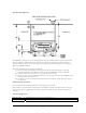
User Manual

5
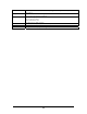
14 DIG3/CNT3 I/O General I/O / external interrupt / counter in
15 GND Ground Ground
16 RTS Output UART RTS
17 RESET# Input Reset (active low)
18 CTS Input UART CTS
19 TCK Input JTAG programming
20 SCK I/O Two-wire interface clock
21 TMS Input JTAG programming
22 SPARE1 I/O General I/O
23 TDI Input JTAG programming
24 Reserved
25 TDO Output JTAG programming
26 Reserved
27 Reserved
28 TXD1 Output UART transmit data
29 Reserved
30 RXD1 Input UART RX
31 Reserved
32 Reserved
33 Reserved
34 FLAG0 Output Initialization
35 Reserved
36 Reserved
37 Reserved
38 VSUPPLY Power Power
39 VSUPPLY Power Power
40 GND Ground Ground
41 GND Ground Ground
J5 Pin OEM100 Signal Type OEM100 Description
1 VSUPPLY Power Power
2 GND Ground Ground
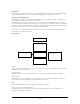
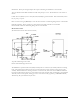
Functional descriptions
Power: The module is powered by a DC power source from 2.0V to 3.3V. The absolute maximum voltage that
should be applied is 3.6V. VCC and VSUPPLY are connected through a zero ohm resistor on the module.
The power plane is attached directly to VCC. P3 can carry 100mA per pin; P5 can carry 500mA per pin.
Ground: These are attached to the ground plane of the module. P3 can carry 100mA per pin; P5 can carry
500mA per pin.
General I/O: These are bidirectional, CMOS level, digital signals running between VCC and GND.
General I/O / external interrupt: These are bidirectional, CMOS level, digital signals running between VCC
and GND. They can also be configured as external, hardware interrupts.
General I/O / external interrupt / counter in: This is a bidirectional, CMOS level, digital signal running
between VCC and GND. It can be configured as external, hardware interrupt or as an input to a counter.
Analog In: These are analog inputs.