
User Manual

4
Connectors
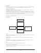
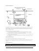
The primary interconnection is P3, the 41 position board to board, header (Hirose p/n DF9A-41P-1V(20);
mates with: Hirose p/n DF9A-41S-1V(20)) on the bottom of the assembly.
Optionally, power can be brought to the board through P5, a two position, right angle wire to board, header
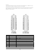
(JST p/n S2B-PH-K-S, mate: JST p/n PHR-2). Here is a schematic drawing of P3 and a list of signal
descriptions for both connectors:
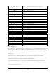
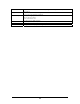
J3 Pin OEM100 Signal Type OEM100 Description
1 GND Ground Ground
2 GND Ground Ground
3 VCC Power Power
4 VCC Power Power
5 GND Ground Ground
6 DIG2/EXTINT2 I/O General I/O / external interrupt
7 SPARE1 I/O General I/O
8 DIG1/EXTINT1 I/O General I/O / external interrupt
9 SPARE0 I/O General I/O
10 DIG0/EXTINT0 Input Initialization
11 AN1 Input Analog In
12 SDA I/O Two-wire interface data
13 AN0 Input Analog In