OAS/EMS NODES
www.sensicast.com
3
33
3-
--
-6
66
6
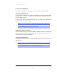
Electrical Interface
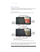
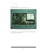
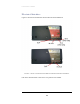
Figure 3-5 shows the electrical interface for the OAS node and the EMS node.
FIGURE 3-5: FRONT OF OAS NODE AND EMS NODE SHOWING ELECTRICAL INTERFACE.
Each of the electrical interface connectors is a two-position screw terminal.