
User Manual
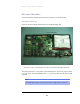
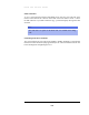
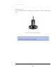
Table Of Contents

MESH AND BRIDGE NODES
www.sensicast.com
2
22
2-
--
-6
66
6
Electrical Interface
The electrical interface includes internal and external connectors, as described below.
Internal Connector
Figure 2-4 shows the internal electrical interface for the Mesh/Bridge node.
FIGURE 2-4: INSIDE OF MESH/BRIDGE NODE SHOWING INTERNAL ELECTRICAL INTERFACE.
The internal connector is a two-position screw terminal used to connect DC power from the
rear of the device. The terminal marked with a “+” sign is the positive lead; the other terminal
is ground.
Note
Acceptable input voltages for the internal connector range from 5V to 13V DC.