
Product Manual


11
WARNING: Do not connect another source of AC power directly to the
output of the inverter. This will result in damage not
covered under warranty.
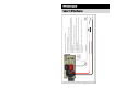
The inverter’s 120 VAC output power is provided at
the GFCI receptacle and the hard wire terminal
blocks behind the access panel.
Wire the AC Input to the hard wire terminal blocks
behind the access panel for charging and shore power.
NOTE: Remove the black hole covers as needed for
hardwire AC wiring. Use a romex type clamp to
protect the wires from the metal edge of the hole.
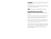
Apply 14.6 in/Lbs torque to the terminal block
screws.
NOTE: Systems rated at 2500 watts and above should be powered with a 30A
circuit.
NOTE: Connecting the plug-in cord to GFCI protected outlets may cause some
interference with the inverter’s GFCI.
NOTE: For GFCI protected hardwire output. Wire directly to the GFCI “Load”
terminals. Verify that you are connecting to the un-used “Load” terminals.
AC INPUT & OUTPUT CONNECTIONS
Tighten to 14.6 in/Lbs