
Product Manual


10
An “Inverter Cable Kit” (positive cable, negative cable, and proper fuse) is needed
to connect the inverter to a battery bank. An 8-guage single strand cable is also
recommended to connect the inverter’s bonding lug to ground.
The inverter cable length and the size of the inverter will determine the cable gauge
and the fuse size to use. The maximum inverter cable recommended is 20-ft; it
must be fused within 18-in from the positive (+) terminal of the battery.
Cross reference the inverter model, and the estimated cable length in the table
below to determine the proper cable gauge and fuse size. An inverter cable kit
designed to SAE guidelines can be purchased directly from our factory – call for
options.
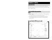
MinimumCableandFusingGuideat3%VoltageDropatFullOutput
Inverter
Model
FullLoad
(AmpsDC)
InvertertoBatteryEstimatedCableLengthinFeet
1 to 10 feet 11 to 15 feet 16 to 20 feet
24NP24 114
2-ga, 250A Fuse 2-ga, 250A Fuse 1-ga, 300A Fuse
24NP36 167
1-ga, 300A Fuse 1-ga, 300A Fuse 2/0, 400A Fuse
NOTE:
• Temp. Comp. cable is part# 611622-XX (XX=length in feet - 9, 15, 20,
25, 30)
To make your own “Inverter Cable Kit,” follow below recommendations:
1. Use stranded copper cables in all cases.
2. USE SGX cross-linked polyurethane insulation type that complies with the
high temperature insulation requirements (125°C.) of SAE J-1127 and vehicle
manufacturer requirements.
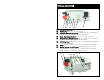
Connect the lug end of the temperature compensation cable to the negative post of
the most negative point in the battery bank. Connect the two pin connector to the
appropriate mating connector located at the side of the inverter labeled “Temp.
Sense.” Use the slide switch on the right side of the inverter and select the battery
type that you are using for proper battery charging.
NOTE: If the temp. Comp. Cable or Dongle is not connected; the battery charger
will not function
DC WIRE GAUGE & FUSING
Inverter Cable
Cable Recommendations
TEMP COMP CABLE CONNECTION