
Product Manual


Page 5
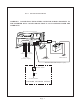
inverter’s output loads, and turns “Off” the
inverter. The second circuit activates the
battery charger and also turns “Off” the
inverter. Both the transfer switch input and
the battery charger input must be the
same phase.
Charger Ratings
Model Input 120VAC, 60Hz Output_
24/2200N Up to 20 Amp AC 50 Amp DC
24/3300N Up to 30 Amp AC 75 Amp DC
24/4800N Up to 30 Amp AC 100 Amp DC
4. START UP / OPERATION
4.01
The battery charger will operate
anytime that there is external AC power
and the battery is not 100% charged. The
status lights will indicate that there is exter-
nal power and the battery’s condition.
4.02 If the unit has the "B1" option, there
are two switches on the right side that
should be set.
4.03 The switch labeled "Battery Type"
should be set to the correct setting based
on the composition of the batteries at-
tached to the inverter. Use the following
table to determine the correct setting.
BATTERY TYPE SELECTION
SETTING BATTERY TYPE
A Vented Nickel-Cadium 10 cells
B Vented Lead-Acid (Antimony)
Flooded Electrolyte
C Sealed Lead-Acid Absorbed or
Vented Nickel-Cadium 9 cell
D Sealed Lead-Acid Gelled
NOTE: Used batteries should be put
through 5 charge cycles with the switch set
one position lower (to the right) than de-
sired. Example: Start a used vented-lead
acid battery on the "C" setting.
4.04 The switch labeled "Battery Size"
should be set to the correct setting based
on the total amp hour capacity of the
batteries attached to the inverter. Use the
following table to determine correct setting.
BATTERY CAPACITY SELECTOR
SETTING AMP HOUR CAPACITY
A Over 600
B 600 - 400
C 400 - 200
D Less than 200
4.05 To operate the inverter, turn the On/
Off switch to “ON”. Assure that the output
breakers are reset. If a remote switch is
used, the inverter is turned “On” or “Off”
by the remote switch.
5. TROUBLESHOOTING
5.01 Sensata offers free phone consulta-
tion concerning installation or troubleshoot-
ing. Call the Customer Service Department
at: 1-800-553-6418 or 651-653-7000
fax: 1-651-653-7600
e-mail: inverterinfo@sensata.com
5.02 If the inverter fails to operate, use
the following troubleshooting procedure.
5.02.1 Connect a 100 watt light bulb to
the inverter output.
5.02.2 Make sure that the inverter is
turned “On”, and the circuit breakers are
reset.
5.02.3 Check the connection to the
remote switch, if used. +24VDC must be
present at the violet wire for the unit to
operate. If not, check any fuses in the
remote switch circuit.
5.02.4 Observe the fault indicating lights
on the front of the inverter.
a) The Low input voltage light indicates a
low battery condition. Switch the inverter
“Off” for 5 seconds, then “On” again. The
light coming on again indicates a fault in the
battery wiring, battery capacity and voltage
or the line fuse.
b) The Overload light indicates an output
wiring short circuit or a load that is too large
for the power rating of the inverter. Switch
the inverter “Off”, remove the short circuit
or excessive load from the output, then
switch the inverter back “On”.