
Product Manual

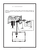

a remote switch may be connected to the
violet wire marked "Remote Switch Hookup"
in the wiring compartment. Disconnect the
violet wire from the battery positive input
terminal. Connect the violet wire to the load
side of the remote switch. The line side of
the switch must be connected to the +24
VDC power source with a fuse within 18" of
the source. The cable clamp strain relief
should be used to secure the field wires.
3.06.4 The switch should be mounted at
a convenient location in a listed outlet box
with approved strain relief.
3.06.5
NOTE:
A remote switch, if
installed, will operate only if the local On/
Off switch on the face of the inverter is
turned "On". You may use several switches
or relays in parallel in lieu of one remote
switch.
3.07 Remote Temperature Sense
( "B1" option)
3.07.1
CAUTION:
Failure to connect
the remote temperature sense probe
correctly will result in high output voltage
that will cause improper battery charging.
3.07.2 A 10 foot long cable with tem-
perature sense probe is provided with the
unit. This allows the unit to know the exact
battery temperature for correct operation
of the temperature compensated circuitry.
This changes the output voltage as required
by the battery at a given temperature.
3.07.3 Install the probe end on a
NEGATIVE battery terminal post.
3.08 120 VAC Output
3.08.1
CAUTION:
Do not connect
another source of AC power directly to the
output of the inverter.
This will result in
damage to the inverter that is not covered
under warranty!
3.08.2 The 120 VAC output of the
inverter is provided at the GFCI receptacle
outlet on the inverter.
3.08.3 The output is also presented
behind the wiring compartment panel using
direct hardwire wire leads. The black wire is
hot, the white wire is neutral and the green
wire is ground. The cable clamp strain relief
should be used to secure the field
wires.
3.08.4 The hardwire A.C. output is not
ground fault circuit interrupt, (GFCI) pro-
tected unless the inverter has option "A".
GFCI outlets should be installed at all appro-
priate locations per NEC 551. The GFCI
outlet should be Hubbell GFR5352XX (20A)
or GFR5252XX (15A).
3.08.5 The remote AC outlets should be
mounted at a convenient location in a listed
outlet box with approved strain relief.
3.09 120/240 VAC Dual Output
(D Option)
3.09.1 The output is presented behind
the wiring compartment panel for direct
hardwire wire leads. The two black wires are
hot, the white wire is neutral and the green
wire is ground. The cable strain relief should
be used to secure the field wires.
3.10 120/240 VAC Input
(T, T1, B1, and D options)
3.10.1 120 or 120/240 VAC (D Option),
60HZ power from the electric utility or
generator can be connected to the inverter
with hardwire connections at the AC Input
wire leads provided in the hardwire compart-
ment. The black wire is hot, the white wire
is neutral, and the green wire is ground. On
the "D" option, the two black wires are hot,
the white wire is neutral, and the green wire
is ground. The cable clamp strain relief
should be used to secure the field wires.
3.10.2 The input circuit should have 30
amp circuit protection from the distribution
panel ("T" option) or 50 amp circuit protec-
tion from the distribution panel ("T1" op-
tion).
3.10.3 When external AC is supplied, the
internal transfer switch is automatically
activated, the inverter is turned “Off”, and
the inverter’s loads will operate from exter-
nal AC input.
3.10.4 Units having the "B1" option
require a separate 120 VAC (240 VAC with
D option) input circuit. The first circuit
activates the internal transfer switch supply-
ing utility or generator power to the
Page 4