
Product Manual


DC Input Wire Lengths
(maximum) and Fusing Guide
Distance(feet)
Model 1-10 11-15 16-20
24/2200N 4 ga 2 ga 1 ga
24/3300N 1 ga 1 ga 1/0 ga
24/4800N 2/0 ga 2/0 ga 3/0 ga
Fuse: 200A 250A 300A 350A 400A 500A
AWG: 4 2 1 1/0 2/0 3/0
3.05.3 NOTE: Using smaller input cable
or longer length will greatly degrade the
inverter peak performance.
IMPORTANT NOTE FOR VEHICLE
INSTALLATION:
Do not use the vehicle
chassis as the negative return in place of a
return cable. Use the same size cable as
the positive connection and run directly to
the battery.
3.05.4 Install the wires at the battery,
inverter and then fuse holder. Make sure
that good, clean connections are made.
Use care not to touch the positive and
negative wires together. This will result in a
violent spark and could result in exploding
batteries and fire.
3.05.5 The battery input terminals are
located in the wiring compartment. A
mounting spark may result when connecting
the battery wire, due to an initial charging of
the internal input capacitor.
3.05.6
CAUTION:
Connecting the
inverter incorrectly to the battery will cause
damage that is not covered under war-
ranty.
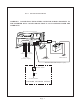
3.06 Remote Switch for Inverter
Operation - Fig. 1
3.06.1 All material used for the remote
switch should be U.L. listed and installed per
low voltage, Class 2, wiring code.
3.06.2 If the "R" option is included, then
connect the cable from the remote panel/
status lights with the mating connector
extending from the inverter. Extention cable
is available if necessary.
3.06.03 If the "R" option is not included,
CAUTION:
Damage to the inverter will
occur if an external AC power source is
applied to the inverter’s AC outlet or its
hardwire output.
CAUTION:
Be sure the inverter's circuit
breaker or fuse (if needed) are turned
"OFF" during installation.
NOTE: All wiring must follow the National
Electric Code, Provincial or other codes in
effect at the time of installation, regardless
of suggestions in this manual. All wires
should be copper conductors.
3.03 Mounting
3.03.1 Locate a suitable, secure vertical
or horizontal mounting surface as close to
the battery as possible without being in the
same air tight compartment. The maximum
recommended distance between the
mounting location and the battery is 20
feet.
CAUTION: If mounting the inverter on a
vertical surface, mount with the front
control panel pointing down.
3.03.2 The location should provide
adequate ventilation and clearance to
maintain room temperature during opera-
tion. At least 1/2 inch of clearance is re-
quired on all sides.
3.03.3 Secure the unit with 1/4 inch
screws or bolts in the mounting slots on the
flanges of the chassis.
3.04 Chassis Bonding Lug - FIG. 1
3.04.1 Connect a #8 gauge or greater
copper wire between the bonding lug on the
inverter and the earth grounding system or
the vehicle chassis.
3.05 Battery Cabling - FIG. 1
3.05.1
CAUTION:
Assure that hydrogen
gas does not accumulate near the battery
by keeping the area well ventilated. A spark
may result when connecting the final bat-
tery wiring due to the initial charging of the
internal input capacitor.
3.05.2 Use stranded copper wire be-
tween the battery and inverter as indicated.
A line fuse must be installed between the
battery and the inverter. U.L. requires that
the fuse be within 18 inches of the battery.
Page 3