
Product Manual


19
Usage: Any 120 VAC, 60 Hz single phase product within the inverter’s power
rating.
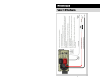
The Display Panel [ON/OFF] key or a voltage between 8 and 20 volts applied to
the “Remote On/Off” input controls the inverter.
Operational modes: “External Power” mode and “Inverter Power” mode.
The LED Display Panel “ON/STBY” LED will be on Green and the Status LED
will blink Amber while the inverter is on. The AC power produced by the inverter
comes from the energy stored in the battery bank through a sophisticated electronic
inversion process. A transformer, a Metal Oxide Silicon Field Effect Transistors
(MOSFET), a filter capacitor and microprocessor control are used to generate clean
AC power.
The inverter will operate at DC input voltages ranging from 10.5 to 17 volts.
Above 17 volts the system will stop operating due to input voltage being out of
range. The inverter can tolerate up to 17V DC input. When the input voltage
drops to 10.5 volts, the inverter will stop operating due to a low battery condition.
When the lead acid battery bank voltage drops to 10.5 volts, the battery is fully
discharged.
Note: The signal output waveform produced by the inverter when in “inverter
mode” is pure sinusoidal. It has a total harmonic distortion of less than 5%.
The LED Display Panel will show charger mode and output and the Status LED
will blink Green indicating that there is a valid external AC power line applied to
the inverter AC input.
Bypass Relay: The loads attached to the inverter output will operate directly from
the external AC power line independently of the inverter ON/OFF status. If the
inverter is left ON (standby mode), the built-in bypass relay will automatically cycle
back and forth between “Inverter Power” mode and “External Power” mode
depending on the availability of the external AC power line.
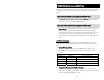
THEORY OF OPERATION
External Power Mode
Inverter Power Mode