
Product Manual


18
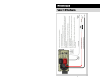
Once the inverter and remote On/Off switch have been fully installed and wired,
and DC power has been applied, the inverter is ready to turn on. The Status LED
on the right side of the inverter shows the status information of the inverter and
charger.
1) Turning the Inverter “ON” or “OFF” (no AC applied):
The inverter can now be turned on by turning on the remote switch. When
the inverter is on the Status LED will blink Amber.
1) Bypass Relay: The loads attached to the inverter output will operate directly
from the external AC power line independently of the inverter ON/OFF
status. If the inverter is left ON (standby mode), the built-in bypass relay will
automatically cycle back and forth between “Inverter Power” mode and
“External Power” mode depending on the availability of the external AC power
line.
BATTERY CHARGER
The battery charger will engage automatically and independently of the inverter
ON/OFF status. The 3-step charging process modes are; Bulk, Acceptance, and
Float.
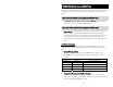
2) Battery Charging Modes
The charger has three modes of operation; Bulk, Accept, and Float. The
Status LED will state which mode the charger is in when shore power is
applied.
Charging Status LED Normal States
LED Color
LED State Operating Conditions
Green
1 blin
k
Bulk Charge
Green
2 blinks
A
ccept Charge
Green
3 blinks Float Charge
Green
4 blinks Load Management Active
3) Temperature Compensation Cable or Dongle
If the temperature compensation Cable or Dongle is not connected to the
“Temp. Sense” connector on the inverter; the battery charger will not function
and the Status LED will blink Red 5 times.
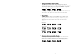
OPERATION (Usin
g
Remote ON/OFF tab)
Inverter Power Mode (Usin
g
Remote ON/OFF tab)
External Power Mode (Usin
g
Remote ON/OFF tab)