
Product Manual


12
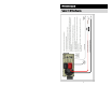
Remote Status Panel
The display panel can be removed from the inverter and installed in a different
location in the vehicle for remote control and monitoring. Please follow the
following procedure closely.
Unscrew the two screws that hold the panel in using a 3/32” allen wrench.
Disconnect the RJ45 connector from the back of the remote panel and re-connect
it to the backside of the replacement RJ45 cover plate.
WARNING: Mount the RJ45 cover plate on the inverter with the two screws
provided in the remote extension kit (8-32x3/8”). DO NOT USE the screws that
held the display to mount the RJ45 cover plate. Using any other screw type or
length than that provided in the kit may damage the inverter and/or harm the
installer. Tighten the screws to 16-17 in/Lbs.
Connect the extension cable to the RJ45 jack and route through the vehicle to the
desired location. See the appendix for mounting hole size and placement
information. Install the remote display panel at the desired new interior location
using installer supplied #8 screws and connect the extension cable to it.
Remote Inverter ON/OFF Switch
An optional customer supplied remote switch can also be used to control the
inverter. Mount the remote switch in a convenient location. Using 18awg wire
and an insulated female faston, wire between the “Remote ON/OFF” connection
on the right side of the inverter and the remote switch. Wire from the remaining
connection on the remote switch to the battery. Make sure to have a 5-amp in-line
fuse installed in series within 10 inches from the positive (+) terminal of the battery.
REMOTE STATUS PANEL & REMOTE INV. ON/OFF SWITCH