
Product Manual


NOMENCLATURE
CASE “L”
16
1.5
2.5
4 5 2.5
15
15.5
CASE “I”
3 93
8.2
15
CASE “O”
17
1.5
2
5.5 4.5 2.5
16
16
MOUNTING THE INVERTER
Installation Tools
Inverter Mounting Recommendations
The following tools are required for inverter installation: Crimper, Cable Ties, Cutter, Drill, #2
Phillips Screw Driver, Tape Measure, Wire Cutters, and Wire Strippers.
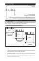
Inverter Mounting Footprints (Dimensions are in inches)
Inverter Models
12/800N & 12/1200N,
& 12/1500N
Inverter Models
12/1800N, 12/2400N
& 12/3000N
Inverter Model
12/3600N
4
NOTE: The inverter mounting location should provide adequate ventilation and clearance to
maintain room temperature during operation. A minimum of 1/2 inch of clearance is required
on all sides.
1. Locate a suitable vertical or horizontal mounting surface as close to the batteries as
possible without being in the same airtight compartment.
2. If mounting the inverter on a vertical surface, the front control panel should be pointing
down whenever possible.
3. Locate the mounting holes on the chassis flanges and fasten them using the 1/4 inch
diameter screws to secure the inverter.