
Datasheet


Page 9
www.sensata.com
Copyright © 2019 Sensata Technologies, Inc.
INSTALLATION INSTRUCTIONS
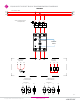
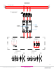
fig.1 SSR mounted on HS053 heat sink
Mounting on Heat Sink
• Select adequate heat sink (see thermal derating curves in product series datasheet).
• Be sure to use a thermal pad (part no. HSP-8) or equivalent thermal compound between the SSR and the selected
heat sink.
• SSR housing mounting holes have a diameter of 0.341in (8.66mm). Two screws are needed to mount the SSR onto
a heat sink (See fig.1). Mounting screws are sold separately as HK8. Otherwise, recommended screw size is 8-32
(socket) using an allen wrench (9/64 in) for the installation. Choose screw length considering mounting surface hole
depth and SSR baseplate thickness of 0.125 in (3.2 mm).
• Before applying full torque tighten down both screws until they contact the baseplate.Then, tighten them to 20 lb-in
(2.2 Nm) min.
• For optimal thermal performance heat sink fins should be oriented vertically to promote natural convection airflow
Mounting on Panel
• Locate the panel section on which the SSR will be mounted. Panel mount surface must provide adequate heat sinking
capability, uncoated, clean, flat (0.004 in/in recommended) and preferably aluminum.
• Be sure to use thermal pad HSP-8 or equivalent thermal compound between the SSR and the panel.
• SSR housing mounting slots have a diameter of 0.341 in (8.66 mm). Two screws are needed (not included) to mount
the SSR onto a panel. Mounting screws are sold separately as HK8. Otherwise, recommended screw size is 8-32
(socket) using allen wrench (9/64 in) for the installation. Choose screw length considering the mounting surface and
that the SSR baseplate thickness is 0.125 in (3.2 mm).
• Before applying full torque tighten down both screws until they contact the baseplate. Then, tighten them to 20 lb-in
(2.2 Nm) min
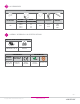
Wiring Instructions
• Recommended wire sizes as shown in TABLE 1
• Maximum terminal screw torque input terminal 5 lb-in (0.5 Nm) (screw terminal only)
• Maximum terminal screw torque load terminal 18-20 lb-in (2.0-2.2 Nm)
• Strip lenght for input terminals: Per manufacturer specifications
• Strip lenght for load terminals: 10mm min.
• Use only copper conductors rated for 75°C
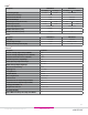
Table 1. Wire Size & Pull Out Strength
Terminal Configuration Recommended Wire Size (Solid/Stranded) Wire Pull-Out Strength (lb)[N]*
Output
1 x 18 AWG (1 mm
2
) [minimum] 20 [88]
1 x 8 AWG (10 mm
2
) 75 [333]
2 x 8 AWG (10 mm
2
) 65 [289]
1 x 3 AWG (26.67 mm
2
)
(1)
90 [400]
Input
Screw
30 AWG (0.05 mm
2
) [minimum] 4.5 [20]
12 AWG (3.3 mm
2
) [maximum] 30 [133]
Spring
(2)
26 AWG (0.13 mm
2
) [minimum] 5 [22]
12 AWG (3.3 mm
2
) [maximum] 5 [22]
*Tests performed on Stranded wire
(1)
Maximum wire size 1 x 2 AWG (35mm
2
)
(2)
Applicable when using CP202 connector instead of supplied connector