
Datasheet


Page 8
www.sensata.com
Copyright © 2019 Sensata Technologies, Inc.
PM6760x50 PM6760x55
PM6760x60 PM6760x75
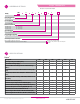
Conditions Description
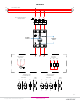
1,11 Initial Condition.
2, 4
Control Input is On, Output is activated,
temperature rises, Green LED is On.
3, 7 Control Input is Off, Output is Off.
5 LED changes to solid Orange color.
6, 9
Output is Off due to overtemperature,
Alarm is latched On, LED changes to
solid red.
7
While Control Input is Off: Output,
Alarm and LED remains Off. (Control
Input Min. 100ms Off to reset values)
8
Control Input is On, Output is on and
temperature rises.
6, 10
Alarm will reset until Control Input
is Off.
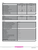
LED
Color
Green
Red
Yellow
* Max. 60 ms OFF when applying PWM on Control Input.
Output On
Alarm
Pre-Alarm
(only for models with overtemperature protection)
TA SUFFIX MODELS
STATUS CHART
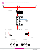
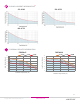
0
10
20
30
40
50
60
70
25 40 80
Load Current (Amps)
0.25 C/W 0.5 C/W 1.0 C/W
Ambient Temperature (ºC)
0
10
20
30
40
50
60
70
25 40 80
Load Current (Amps)
0.25 C/W 0.5 C/W 1.0 C/W
Ambient Temperature (ºC)
0
10
20
30
40
50
60
70
80
25 40 80
Load Current (Amps)
Ambient Temperature (ºC)
0
10
20
30
40
50
60
70
80
90
25 40 80
Load Current (Amps)
0.25 C/W 0.5 C/W 1.0 C/W DR670.25 C/W 0.5 C/W 1.0 C/W DR67
Ambient Temperature (ºC)