
User Manual

Introduction
e CO2 transmitter uses Infrared Technology to monitor CO2
levels within a range of 0 – 2000 ppm and outputs a linear 4-20
mA signal. Features include a back-lit LCD and user menu for
easy installation
Before Installation
Read these instructions carefully before installing and commis-
sioning the CO2 transmitter. Failure to follow these instructions
may result in product damage. Do not use in an explosive or
hazardous environment, with combustible or ammable gases,
as a safety or emergency stop device or in any other application
where failure of the product could result in personal injury. Take
electrostatic discharge precautions during installation and do not
exceed the device ratings.
Mounting
e room type sensor installs directly on a standard electrical
box and should be mounted ve feet from the oor of the area
to be controlled. Do not mount the sensor near doors, opening
windows, supply air diusers or other known air disturbances.
Avoid areas where the detector is exposed to vibrations or rapid
temperature changes.
e cover is hooked to the base at the top edge and must be
removed from the bottom edge rst. Use a small screwdriver to
carefully pry each bottom corner if necessary. If a security screw
is installed on the bottom edge, then it may have to be loosened or
removed also. Tip the cover away from the base and sit it aside.
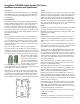
e pcb must be removed from
the base to access the mounting
holes. Follow usual anti-static
procedures when handling the
pcb and be careful not to touch
the sensors. e pcb is removed
by pressing the enclosure base to unsnap the latch near the
bottom edge, then the pcb can be lied out of the base. Sit the pcb
aside until the base is mounted on the wall.
Aer the base is screwed to an electrical box or the wall using
the appropriate holes, pull the wires through the wiring hole in
the center of the pcb and then reinstall it in the enclosure base.
Ensure the pcb is snapped into the base securely and correctly.
e mounting hole locations are shown in the following drawing.
Start Up
Verify the transmitter is properly wired and connections are tight.
Ensure the output switch is set for mA. Apply power and note that
the CO2 sensor chamber light ashes on and o. e LCD will
indicate the soware version number, the output signal type, the
CO2 measurement range and then the sensor will begin reading
the CO2 level, output the correct analog signal and display the
value on the LCD. e sensor operates on a 4 second interval and
will update the output and display every 4 seconds.
Output
e CO2 output is scaled such that 4-20mA equals 0 to Out_High
as set in the Setup Menu. e factory default is 0-2000 ppm.
Out_High can be changed from 1000 to 7500 ppm and the output
signal is scaled accordingly.
Calibration
Calibration with gas requires a eld calibration kit consisting of
an LCD, a bottle of 1000 ppm CO2 gas, a tank pressure regulator
with ow restrictor and the necessary tubing to connect to the
device.
Note that because of the Automatic Calibration Mode and other
technology incorporated into this sensor, only a single point 1000
ppm calibration is required to meet specied accuracy.
Turn the regulator on/o knob fully o and attach it to the 1000
ppm CO2 gas bottle and rmly tighten it by hand. Remove the
cover of the unit to be calibrated to expose the gas sensor cham-
ber. e tubing from the gas bottle can be connected to either port
on the chamber aer the plastic cap is removed. Gently remove
one cap and connect the tubing, note that strong shock or vibra-
tion can aect calibration.
Ensure the device has been operating normally for at least ve
minutes before applying gas. Slowly turn the valve knob on the
regulator to let the gas begin owing.
e regulator will restrict the ow rate to the specied 100 ml/
min. Aer a brief period the gas will ow into the chamber and
the CO2 reading on the LCD will begin to approach 1000 ppm.
Wait 1 to 2 minutes until the CO2 reading stabilizes.
Enter the Setup menu and use the <MENU> key to advance to
Calibrat 1000 PPM. Press and hold the <SAVE> key for 2 seconds
and the display will change to Waiting Calibrat then to Waiting 5
minute to indicate that the process of reprogramming the internal
calibration setting is taking place.
is calibration process takes about 5 minutes and the LCD will
count down the minutes. Do not disturb the unit or the gas ow
during this period. When calibration is complete the unit will
display Calibrat Done. Press the <SAVE> key to return to normal
operation and then the gas can be shut o.
Disconnect the tubing and replace the cap on the sensor chamber
as calibration is complete.
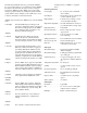
Setup Menu
e menu has several items as shown below. To enter the menu,
press and release the <MENU> key while in normal operation.
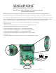
Sensaphone FGD-0068 Carbon Dioxide (CO
2
) Sensor
Installation Instructions and Specifications