
Operating instructions


LMA-1250-LP “DEFLECTOMETER
TM
” Series Operating Instructions
Low Power Single Channel / Dual Output Inductive Loop Vehicle Detector
102112 Eberle Design Inc. Page 2
pn 888-1251-001 3510 E Atlanta Avenue, Phoenix, AZ 85040 USA
Tel: 480-968-6407 Web: www.EDItraffic.com
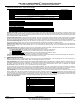
LMA-1250-LP Parameter Options – Eight Position DIP Switch
SWITCH
ON
OFF
FACTORY DEFAULT
1 Sensitivity Boost No Sensitivity Boost OFF
2 Limited Presence Infinite Presence OFF
3 2-Second Delay Timing No 2-Second Delay Timing OFF
4
See “Extension Timing” Table Below (Switches 4 & 5)
OFF
5 OFF
6 See “Output B Mode” Table Below (Switches 6 & 7) OFF
7 OFF
8 Output A No Detect in Fault Mode (fail secure) Output A Detect in Fault Mode (fail safe) OFF
Extension Timing (Switches 4 & 5)
SWITCH
0 Seconds
2 Seconds
5 Seconds
10 Seconds
4
0FF
ON
OFF
ON
5 0FF OFF ON ON
Output B Mode (Switches 6 & 7)
SWITCH Pulse On Entry Pulse On Exit Duplicate Output A ON During Loop Fault
6 0FF OFF ON ON
7 0FF ON OFF ON
Sensitivity Boost (DIP 1): When ON, sensitivity will increase only during the CALL Output period without changing the sensitivity of a vacant loop. When a vehicle
enters the loop, the LMA-1250-LP sensitivity is boosted to a higher level than the vacant loop setting. The boosted sensitivity remains throughout the CALL Output
period. When the vehicle leaves the loop, the sensitivity returns to the vacant loop setting. This feature helps prevent dropouts during the passage of high bed vehicles
and is exceptionally useful in sliding gate situations.
Presence Output Modes (DIP 2): When ON (Limited Presence Mode), the presence CALL Output A hold time is between 5 minutes minimum and 3 hours maximum.
Hold time depends on loop geometry; number of wire turns in the loop, vehicle size, and position of the vehicle in the loop zone. When OFF (Infinite Presence Mode),
the presence CALL Output A hold time will always be maintained as long as a vehicle is located over the loop zone and power is not removed from the LMA-1250-LP.
Two Second Output Delay (DIP 3): When ON, the CALL Outputs A & B will be delayed for a period of 2 seconds after a vehicle has entered the loop zone. If the
vehicle does not remain in the loop zone for the full 2 seconds the delay timer will terminate and no CALL Output A or B will be produced.
Output Extension (DIPS 4 & 5): Utilizing the settings shown in the “Extension Timing” DIP switch table above, or the label located on the side of the LMA-1250-LP,
the Output A can be selected to hold a CALL output for either 2, 5 or 10 seconds after the vehicle has left the loop zone. This feature does not affect Output Pulse
modes or Output B.
Output B Mode (DIPS 6 & 7): Utilizing the settings shown in the “Output B Mode” DIP switch table above, or the label located on the side of the LMA-1250-LP, four
output modes of operation are selectable for Output B. Output A always operates in Presence mode.
In the Pulse on Entry Mode, the Output B provides a 250-millisecond pulse when a vehicle enters the loop zone.
In the Pulse on Exit Mode
, the Output B provides a 250-millisecond pulse when a vehicle exits the loop zone.
In the Duplicate Output A Mode, the Output B operates in presence mode and follows the operation of Output A.
In the ON During Loop Fault Mode, the Output B is On during a current loop fault condition.
Output A Mode (DIP 8): When ON (Fail Secure Mode), the Call Output A is Off during a current loop fault condition. When OFF (Fail Safe Mode), the Call Output A is
On during a current loop fault condition. Output A is always Off (Fail Secure) for a loss of power.
6. Additional Features & Benefits
Reset: The LMA-1250-LP can be manually cleared and retuned by pressing the front panel RESET button or by interrupting power. The current loop frequency is
displayed immediately after pressing RESET (flashing digits). See “Measuring Loop Frequency” in section 5.
Loop Fault Diagnostics: The LOOP FAULT indicator and 7-Segment DEFLECTOMETER
TM
indicate if the LMA-1250-LP is within the specified loop inductance range. The
LMA-1250-LP is able to detect Open Loops, Shorted Loops, or sudden changes in loop inductance exceeding 25% of the nominal inductance. If a Loop Fault is detected,
the OUTPUT and LOOP FAULT indicators continuously emit a sequence of flashes (See the “LED Indications” table in section 3). Additionally, the 7-Segment
DEFLECTOMETER
TM
displays the code “F1”, “F2”, or “F3” indicating a current loop fault condition.
If a fault condition self-heals, the OUTPUT indicators and the 7-Segment DEFLECTOMETER
TM
will return to normal operation. The LOOP FAULT indicator will continue to
flash with the sequence signifying the type of loop fault that was last detected. In the case of the excessive inductance change fault, the unit will retune to the new
inductance after a period of two seconds and continue operation. Pressing the RESET button will clear the flash sequence from the LOOP FAULT indicator.
Loop Fault Memory: Previous loop faults are stored in non-volatile internal memory. If power is interrupted for any length of time, the LMA-1250-LP will not lose the
last loop condition status. After power is restored to the LMA-1250-LP, the yellow LOOP FAULT indicator will automatically
indicate the last loop status condition (Open
Loop, Shorted Loop, 25% Change In Inductance, or No Loop Problem. See the “LED Indications” table in section
3. Momentarily pressing the front panel RESET button
will clear the LOOP FAULT indicator and retune the LMA-1250-LP. Should you want to review the last loop condition after the LMA-1250-LP has been reset, simply
PRESS and HOLD the RESET button and after 2 seconds the LOOP FAULT indicator will indicate the last loop fault condition.
7. Connector Pin Assignments:
PIN
FUNCTION
1
12 VDC to 24 VDC / 24 VAC (+)
2 DC Ground / 24 VAC (-)
3 Output Relay B, Normally Open (Closes for DETECT)
4 No Connection
5 Output Relay A, Common
6 Output Relay A, Normally Open (Closes for DETECT)
7 Loop Input
8 Loop Input
9 Output Relay B, Common
10
Output Relay A, Normally Closed (Opens for DETECT)
11 Output Relay B, Normally Closed (Opens for DETECT)
Deflectometer is a trademark of Eberle Design Inc.