
User`s guide


85
LOCKOUTS:
When a safety shutdown occurs, the control will indicate the reason for the lockout through the
Alarm/Status LED and also describe the lockout on the User Interface. The alarm relay located on
terminals P4.1 to P4.2 will be energized. The non-volatile memory will remember the status (Run or
Lockout) of the control even if a power failure occurs. By momentarily depressing and releasing the
reset button located on the User Interface or through a programmable digital input, the control can be
reset. The button must be held down for one second and then released. Very little force is required to
do this. Do not press hard.
The action of a lockout will cause the safety relay output located at terminal P5.9 to P5.10 to be de-
energized thus opening the non-recycling interlock in the flame safeguard circuit. This is followed
by all other relays in the PPC4000 moving to a de-energized state.
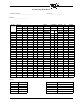
ERROR MESSAGES:
The following list provides error codes and explanations to help people in the field respond more
effectively to issues that arise.
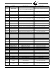
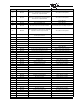
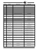
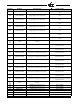
Error Code Displayed Reason for error Possible remedy
e1 PPC4000 FAULT ARM CPU self-test Replace PPC4000
e2 PPC4000 FAULT ARM CPU code CRC Replace PPC4000
e3 Z BOARD FAULT PPC4000 cannot communicate with the Z board Check or replace Z board
e4 SAFETY RELAY ON
This means that there is an active line voltage on P5 pin
9, when there shouldn't be. This could be as a result of
a wring problem or the internal safety relay contacts are
welded.
Check wiring to specific terminal
e5 SAFETY RELAY OFF
This means that the system is not sensing a live/inter-
lock voltage on its safety relay input. This could be as a
result of a wiring problem, no line voltage to P5 pin 10,
or the safety fuse is blown.
Check Fuse
e6 RELAY 8 ON
This means that there is an active line voltage on P5 pin
2, when there shouldn't be. This could be as a result of
a wring problem or the internal HIGH FIRE relay con-
tacts are welded.
Check wiring to specific terminal
e7 RELAY 8 OFF
This means that there is NO active line voltage on P5
pin 2. This could be as a result of a faulty HIGH FIRE
relay or the contacts are bad.
Replace PPC4000
e8 RELAY D ON
This means that there is an active line voltage on P5 pin
1, when there shouldn't be. This could be as a result of
a wring problem or the internal LOW FIRE relay con-
tacts are welded.
Check wiring to specific terminal
e9 RELAY D OFF
This means that there is NO active line voltage on P5
pin 1. This could be as a result of a faulty LOW FIRE
relay or the contacts are bad.
Replace PPC4000
e10
Unused Unused
e11 INVALID PROFILE
The user is supplying line voltage to more than 1 of the
following P15-5,6,7,8
Check wiring
e12 HIGH TEMPERATURE Internal Temperature is above 80C Check Fan or provide better ventilation
e13 CHECK WIRING
User supplying line voltage to terminal to more than
one of the following terminals at one time: P15-2,3,4
Check wiring
e14 CHECK WIRING
User has not connected one or more of the following
terminals: P15-2,3,4
Check wiring
e15 NO AIR SERVO
The user has no servo named "AIR" in the
current profile
Name one servo in current profile "AIR"