
User`s guide


72
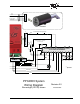
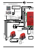
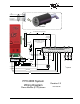
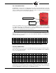
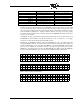
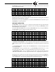
FIGURE 11. System Wiring Diagram (E110)
NXD410 (front)
NXD410 (rear)
1
1
1
1
1
Display Tx (Yellow)
Shield
Twisted
Pairs
Jacket
Drain
Display Ra (Orange)
Display Rb (Brown)
Display Ty (Blue)
24Vdc (Red)
24Vdc Return (Black)
Servo B (RS-485 -)
Servo A (RS-485 +)
Jacket
1
Daisy
Chain
Wiring
To Next
Servo
6
7
14
15
P2
P12
P11
P13 P3 P15
24Vdc
PCV
24Vdc (Red)
24Vdc Return (Black)
24 Vdc (Red)
24 Vdc Return (Bla
1
2
3
4
5
6
7
9
10
8
11
2
3
4
5
6
7
8
9
10
11
1
1
1
12
10 1211
2
3
8
97
65
4
1
1
2
1
1
3
2
1
1
1
6
5
4
3
1
2
TDB-
TDB+
59-562-2
Burner Switch
and other
Recycling Running
Interlocks
FX20-1
(ORG)
(BRW)
All drain wires to be attached to
grounding screw (EARTH)
++
-
AUX
1
PCV
T
P
T
P
P
T
-
AUX1
Earth ground and
all drain wires
connect here.
Consult the NXTSD-4001
bulletin for connection to
a touchscreen.