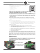
PPC-4001 SEPTEMBER 15, 2014 PPC4000 SERIES FUEL AIR RATIO CONTROLLER DESCRIPTION Fireye PPC4000, the newest member of the Nexus family, is a state of the art parallel positioning system for all types of liquid or gaseous fuel fired combustion systems. When combined with a Fireye flame safeguard system such as the Fireye BurnerLogix control, the PPC4000 offers the most compact and advanced parallel positioning system available.
quickly check key system values while in commissioning mode. The NXD410 is panel mount only and is rated for NEMA 4X indoor environments. When required, the operating system of the PPC4000 and NXD410 will automatically direct the user to the passcode setup screen and when entered correctly will take the user directly to the parameter requested, making the entire system user-friendly.
Warning: Electro-mechanical high steam pressure or high water temperature limits must remain in the running interlock circuit of the flame safeguard control. This manual describes the installation, commissioning, operation and maintenance of the PPC4000 series fuel air ratio controls.
TABLE OF CONTENTS Description . . . . . . . . . . . . . . . . . . . . . . . . . . . . . . 1 Flue Temperature Alarm Limits . . . . . . . . . . . . . 46 Key Features of the PPC4000 System . . . . . . . . 2 Gain Terms . . . . . . . . . . . . . . . . . . . . . . . . . . . . 47 PPC4000 System Specifications . . . . . . . . . . . . . 5 Understanding O2 Error Codes. . . . . . . . . . . . . 47 Approvals . . . . . . . . . . . . . . . . . . . . . . . . . . . . . . . 7 Commissioning Procedure . . . . . . . .
PPC4000 SYSTEM SPECIFICATIONS PPC4000 Control: Supply Voltage: PPC4000 120 VAC (+10%, -15%) 50/60 Hz Power Consumption: 15 VA Temperature Rating: Operating: 32°F to 140°F (0°C to 60°C) Storage: -4°F to 158°F (-20°C to 70°C) Humidity Rating: 85% RH, non-condensing Protection Category: NEMA 1 (IP01) Unit Dimensions: 5.0" (127 mm) W x 8.0" (203.2mm) H x 4.0” (101.6mm) D Shipping Weight: PPC4000: Approx. 3.2 lbs. (1.
Unit Dimensions: Panel Cutout: 13.22 (336mm)L x 10.51 (267mm)H Shipping Weight: Approx. 6.2 lbs. (2.8 kg) NXCESO2 Oxygen Probe: Supply Voltage: 24 VDC ± 10% Power Consumption: 27 VA, 13 VA (steady state) Temperature Rating: Operating: 32°F to 140°F (0°C to 60°C) Storage: -4°F to 158°F (-20°C to 70°C) Humidity Rating: 85% RH, non-condensing Protection Category: NEMA 1 (IP01) Unit Dimension: see Figure 6 on page 23 Shipping Weight: NXCES02-8: 8.1 lbs (3.67 kg) NXCES02-16: 9.2 lbs (4.17kg) NXCES02-30: 11.
Temperature Sensors: Temperature Measurement Range: FXIATS-140: -40°F to 140°F (-40°C to 60°C) - see FXIATS-1 bulletin for technical info TS350-X: 32°F to 350°F (0°C to 176°C) TS752-X: 32°F to 752°F (0°C to 400°C) RTD Type: Platinum, 100 ohms ± 0.1% @32°F (0°C) Temperature Coefficient:.00385 ohms/°C Output: 4-20 mA, linear with temperature Operating Temperature Range: -13°F to 185°F (-25°C to 85°C) Accuracy: ± 0.
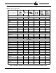
PART NUMBERS AND APPROVALS Table 1: Agency Approvals Fireye Part Number Control PPC4000 X X X User Interface NXD410 X NXTSD407 X NXTSD413 X Servos FX04, FX04-1 X X X FX20, FX20-1 X X X FX50, FX50-1 X X X Oxygen Probe NXCESO2-8 NXCESO2-16 NXCESO2-30 Transducers BLPS-15 X X BLPS-25 X X BLPS-30 X X BLPS-200 X X BLPS-300 X X TS350-2, -4, -8 X X TS-752-2, -4, -8 X X FXIATS-140 X Flame Safeguard YB110UV X X X X X X YB110UVSC X X X X X X YB110IR X
ORDERING INFORMATION Control PPC4000 Parallel positioning system, 120 VAC input. Used with flame safeguard control NXCESVFD Plug-in assembly provides variable frequency (VFD/VSD) capability 60-2926 Enclosure, 12.5” x 10.5” x 6.5”, UL listed, fitted for PPC4000 129-190 Kit, fan replacement NXD410 User Interface with keypad, 24 VDC operation, 4 line back lit LCD display, panel mount only, includes mounting brackets.
INSTALLATION PROCEDURE 1) A UL listed fuel/air ratio system is comprised of the following items. a.) PPC4000, fuel/air ratio controller b.) 60-2926, enclosure c.) NXD410, user interface d.) FX series servos 2) Wiring must comply with all applicable codes, ordinances and regulations. 3) Wiring must comply with NEC Class 1 (Line Voltage) wiring. 4) To minimize interference from radio frequency energy generated by the PPC4000 control, it is necessary that all control wiring be placed in conduit.
FIGURE 1. Mounting Kit Completed Assembly Gasket Fastening Screw Bracket Fastening Nut Bracket mounting locations (4 places) Peel paper from gasket surface The bracket assembly mounts from the rear of the display with the fastening nut against the backside of the panel. Use the following dimensions for the panel cutout. FIGURE 2. Panel Cutout 3.78” (96mm) PLC Port 5.35” (136mm) Use Fireye cable, part number 59-562-2 to connect from the NXD410 to the PPC4000 control.
P15 1. TBD 2. HIGH 3. LOW 4. AUTO 5. P4 6. P3 7. P2 8. P1 P13 1. DI 10 2. DI 9 3. DI 8 4. DI 7 5. DI 6 6. DI 5 7. DI 4 8. DI 3 9. DI 2 10. DI 1 11. TBD 12. TBD SD ACTIVITY P1 3 P1 5 P5 P3 P4 P3 L1 - LINE IN L2 - NEUTRAL EARTH P4 1. ALARM IN 2. ALARM OUT 3. OCRC IN 4. OCRC OUT 12 STATUS/ALARM P5 10. KS In 9. P 8. TBD 7. TBD 6. TBD 5. TBD 4. TBD 3. AUX 2. 8 1.
P12 1. mbus A 2. mbus B 3. seq A 4. seq B 5. servo A 6. servo B 7. dis TX,ye 8. dis TY,bl 9. dis Rb,br 10. dis Ra,or 11. O2 A 12. O2 B P14 top P13 1. DI 10 2. DI 9 3. DI 8 4. DI 7 5. DI 6 6. DI 5 7. DI 4 8. DI 3 9. DI 2 10. DI 1 11. 12. P14 bottom P14 1. encoder (2) 2. encoder (1) 3. 4-20 in (2) 4. 4-20 in (1) 5. 4-20 out (2) 6. 4-20 out (1) 7-12 common pin 1 2 3 4 5 6 7 8 9 10 11 12 P14 P15 P12 P11 P13 P2 P4 P4 1. ALARM IN 2. ALARM OUT 3. OCRC IN 4. OCRC OUT P3 P2 1. 24 vdc 2. 24 vdc Servos 3.
PPC4000 INSTALLATION Install the PPC4000 control where the relative humidity never reaches the saturation point. The Nexus PPC4000 system is designed to operate in a maximum 85% relative humidity continuous, non-condensing environment. Do not install the PPC4000 system where it can be subjected to vibration in excess of 0.5G continuous maximum vibration. The PPC4000 system is not a weather tight enclosure. The standard vertical position is recommended.
The PPC4000 is mounted to the cabinet back plate using 4 X #8-32 screws. Following the mounting dimensions shown in Figure 4, drill and tap 4 mounting holes. Firmly screw the control to the cabinet back plate. WIRING CONNECTIONS Terminal Type Description P3.1 L1 Line Voltage Supply P3.2 L2/N Line Voltage Common EARTH (stud) Rating/wiring 120 VAC (+10%, -15%) 50/60 Hz Protective Earth Chassis ground connection Voltage free contacts P4.1 Input Alarm Relay Input P4.
Terminal Type Description Rating/wiring P13.1 D1 10 Digital Input #10 120 VAC @ 1mA P13.2 D1 9 Digital Input #9 120 VAC @ 1mA P13.3 D1 8 Digital Input #8 120 VAC @ 1mA P13.4 D1 7 Digital Input #7 120 VAC @ 1mA P13.5 D1 6 Digital Input #6 120 VAC @ 1mA P13.6 D1 5 Digital Input #5 120 VAC @ 1mA P13.7 D1 4 Digital Input #4 120 VAC @ 1mA P13.8 D1 3 Digital Input #3 120 VAC @ 1mA P13.9 D1 2 Digital Input #2 120 VAC @ 1mA P13.
PPC4000 MOUNTING AND WIRING As a convenience, the PPC4000 is equipped with de-pluggable type terminal blocks. It is recommended the PPC4000 be wired with the terminal blocks inserted into the control as shipped. Following the wiring connections table above, make all electrical connections in accordance with the application requirements. The suggested order of wiring is as follows: 1. Power inputs, L1, L2, Earth (AWG 18, 300 vac) P3.1, P3.2 2. NXD410 user interface using Fireye cable 59-562-2 P12.7-P12.
Table 2: SENSOR RANGE and SETTINGS Part Number Sensor Type Set Point Range 1.0 - 14.0p 70m - 950m Mod Range Increment Decrement Cut In Cut Out 0 - 6.0p 0 - 410m 0.3 - 6.0p 20m - 410m 0.3 - 6.0p 20m - 410m 0.1p 10m BLPS-15 0 - 15 PSI 0 - 1030m BLPS-25 -14.7 - 25 PSI 1.0 - 23.0p -1013 - 1720m 70m - 1500m 0 - 6.0p 0 - 410m 0.3 - 6.0p 20m - 410m 0.3 - 6.0p 20m - 410m 0.1p 10m BLPS-30 0 - 30 PSI 0 - 2070m 1.0 - 28.0p 70m - 1950m 0 - 6.0p 0 - 410m 0.3 - 6.0p 20m - 410m 0.3 - 6.
MOUNTING TEMPERATURE SENSORS The immersion style temperature sensors have a ½” NPT mounting for the 2", 4", and 8" thermowell probes, and a ½” conduit fitting for electrical connections. WARNING: Location of the temperature sensor to monitor boiler water temperature of a steam boiler is critical. The sensor should be mounted where it is always exposed to the circulation of the boiler water, not too close to a hot or cold inlet or steam coil.
SERVO MOTOR SETUP AND WIRING The PPC4000 must have a “master servo” in order to generate a valid modulation curve. In a typical setup, without VFD, the AIR servo is selected as the master servo; if a VFD is used, the first fuel servo is then selected as the master servo. The modulation rate, low fire to high fire, and therefore the servo(s) positions are derived from the master servo commissioning values.
Note: The PPC-4000 provides two terminals for 24 Vdc supply for the servos P2.2 & P2.3 (24 Vdc return via P2.4P2.6). The PPC-4000 can supply approximately 60 VA through these terminals1, for any combination of connected servos. The PPC-4000 can supply up to twelve 4Nm servos or four 20Nm servos, or three 50Nm servos or some combination that will result in 60 VA of power2. If more power than this is required, an external power supply must be used3.
NXCES02 OXYGEN PROBE The NXCESO2 oxygen sensing probe is designed to operate with the PPC4000 and provides trimming of the air or fuel servos to maintain predefined O2 target levels resulting in optimum combustion. Refer to Commissioning and Adjust Ratio procedures. The NCESO2 also provides the stack temperature measurement. The user has the option to activate both O2 level and flue temperature level alarms and the alarms can be selected to be warning or lockout.
NXCESO2 Dimensional Information FIGURE 6. CLEARANCE REQUIRED TO REMOVE AND INSTALL FROM FLUE . SEE DIM "C" SEE DIM "B" FROM FACE OF MOUNTING FLANGE 119.4 4.70 OVERALL VERTICAL DIM SEE DIM "Y" 1/2 NPT CONDUIT ENTRY SEE DIM "A" CLEARANCE REQUIRED TO REMOVE AND INSTALL. FROM FLUE. SEE DIM "D" FLUE GAS OVERALL HORIZONTAL DIM SEE DIM "X" 38.10 1.50 MODEL NUMBER DIM "A" DIM "B" DIM "C" DIM "D" DIM "X" DIM "Y" NXCES02-8 ( 44) 1.69 (216) 8.50 (426) 16.75 (324) 12.75 (445)17.50 (121) 4.
NXD410 User Interface The NXD410 User Interface provides the means to setup, monitor and display all information from the PPC4000 Control and connected accessories. The NXD410 provides a four line backlit LCD display screen and a multi-function tactile feel keypad. The NXD410 is panel mounted and connects directly to the PPC4000 using Fireye cable 59-562-2. Explanation of NXD410 keypad The > and < characters act as alignment indicators.
The NXD410 and PPC4000 Control contain a number of Quick Keys that allow the user to access that function directly. For these Quick Keys to operate the installer or operator must first access the KEYPAD SETUP menu where the user defines if a Quick Key is used or unused. Quick Keys are also non-volatile meaning the state of the switch function is retained in memory should a power recycle occur. No LED Key Name Description 1 BURNER ON/OFF KEYPAD SETUP required. Used to turn the burner ON or OFF.
The HOME key is used to bring the user directly back to the top layer menu and display the default items. Any item in the top layer menu that contains a > character indicates there is a sub menu below it. The NEXT key is used to move to the next sub menu showing parameters for that item. The BACK key is used to revert from the sub menu back to the previous level menu. Various menu items may have several sub menus.
The UP and DOWN keys are used to scroll forward and backward through the top layer menu. The menu is continuous in both directions. That is, when you reach the bottom and continue with the DOWN key, for example, the very top of the menu will be displayed on the next line. As stated earlier, hitting the HOME key from anywhere will bring you back to the HOME screen. The shaded area shown in the Top Layer Menu section on page 25 is the HOME screen.
On first application of power, with conditions as stated above, the display will indicate: > S S M M T E E O A T A D N P S U D O U L B I R A Y N E T T D I O V N A L R A T U U E N N U U s S S 0 E E 0 1 D D % < The Operating control relay (OCRC) will remain open and the servos will remain at their respective installed positions. For PASSCODE protected parameters, if the passcode is not enabled, the user will be automatically directed to the PASSCODE setup screen.
The PPC4000 uses 12 hour format only, AM / PM. If the clock and date need adjustment, the NEXT key is pressed to move to the DATE / TIME SETUP submenu. > < S S S S S S D E E E E E E A T T T T T T T E Y M D H M S / E O A O I E T A N Y U N C I R T M H R U O T N E S E T U P 2 0 J 1 2 1 A 0 P E D 1 N 1 M 0 0 < Use the UP / DOWN keys to position the item to be modified between the > < marks and use the MDFY/SAVE key to modify and save the new value.
The first parameter that must be set is to name the servo. Each servo must be named and at least one servo of each profile must be named AIR. The table below lists the options for naming the servo and also to what profiles the servo is tagged.
the servo, press MDFY and using the UP and DOWN keys, set the target position. In this example set the target position to 10.0 degrees. Press SAVE and the display will indicate the original position and change as the servo is moving toward its target position. The final display for servo 1 should look like the following: > < S A D S S E S I E E R S R R R V I E V V O G C O O N T N M I P 1 A E O O M N N S E T I T I O N 1 0 A I .
For this application, at SENSOR TYPE press MDFY. Use the UP or DOWN keys to select STEAM and press SAVE. At SENSOR RANGE, press MDFY and use the UP or DOWN keys to select 15 PSI and press SAVE. The display will be as follows: > < T R S Y A E P N N E G S O R 1 E 0 t S 1 o T 5 E p A s M i < See table 2 for sensor range and settings. Press the BACK key twice to get back to the top layer at the point where we left it or press HOME to go directly back to the HOME screen.
Definitions: LIMIT TYPE DEV - Values that deviated from setpoint. The advantage is these values will float with the setpoint. SETPOINT - The target pressure or target temperature the control will maintain. CUT IN (Cut In Value) - Determines the point in which the steam pressure (or water temperature) must reach to start a burner cycle. In DEV option, this a differential value that is subtracted from the steam pressure or water temperature setpoint.
HIGH LIMIT - When this is exceeded, the PPC4000 will proceed to lockout. The user programs both HIGH MARGINAL and HIGH LIMIT for the temperature or pressure sensors based on the input signal received. The HIGH MARGINAL cannot be set higher than the HIGH LIMIT nor can either be set lower than the sum of SETPOINT plus CUT OUT. Alarm points for stack monitoring can be set anywhere within the sensor range. Both INTEGRAL and DERIVATIVE terms are used to eliminate steady-state error and reduce overshoot.
PROFILE SETUP In the top layer scroll to PROFILE SETUP and press NEXT to enter this sub menu. This menu provides the means to name the profile, set the maximum modulation rate for this profile and when necessary erase the profile setpoints. > < P P P P E P R R R R R R O O O O A O F F F F S F I I I I E I L L L L L E E E E A E L S 1 2 3 4 L E T U P N N N N D A T A E T U P O O O O N N N N E E E E N > > > > O < N 1 O 0 N 0 N E % O < Using the NEXT key, select PROFILE 1.
The list of general purpose functions for all digital inputs is as follows: > S M O S B E A 2 F E F S U T L R P O N U T R B R Q O T O E N O W A A R C A C U E I L L I E C E E R N F A C T I R M M D K N S C R M O D S O E I U O 2 E D I E V Q N N N R U S T E U T S H E L A B R M G S R L O S A B A I S O E O C L E T L C D T F D L T D T E E K E R F < If DIGITAL INPUT 1 (DI1) is to be set as BURNER CONTROL, at DI1 press the NEXT key to display the following: > < U A D S C I E T 1 S E
VARIABLE FREQUENCY DRIVE In addition to using a precision servo motor to control the air flow into a combustion chamber, the PPC4000 can control one or two variable frequency drives (VFD/VSD) with the result being better control over air flow and improvements in combustion. Electrical energy savings and additional gains P14 pin 1 in efficiency are quickly realized when controlling the combustion blower motor with a VFD.
Each VFD channel has its own separate and independent sub menu. The following assumes that VFD2 is moved between the two tick marks and the NEXT key is pressed to display the following configuration menu. < V A D E R G I T A S V V F S I N U A N O C T F F D S S C N I T L C O D D I P O N E E E P N G L D M G R L 2 2 A N A E O R A / T M M Y R D E E A N D I P L C E M O N F C T O O R U M N A T 4 T S , 3 E E , N 1 A 1 F 2 C 0 U . 0 E C E S H E L I T I O N I 3 A , O 0 T 0 .
b. Integral is the time between error corrections or updates to the VFD. A high rate of updates (short integral time) to the VFD can result in unstable operation. Conversely too few updates (long integral time) to the VFD can result in large deviations from setpoint. Update time to the VFD output is done at ¼ second intervals. The range of value for INTEGRAL is 0 to 100 in increments of 0.1 with a default of 0.0. The lower the setting, the shorter the integration time will be. The default setting of 0.
4. Making modifications to any of the VFD parameters in the servo setup submenu, requires the Commissioning pass code to be enabled. 5. Attempting to change a VFD channel to a value other than UNUSED in the ANALOG OUT sub menu while its ASSIGNMENT > 0 in the SERVO SETUP sub menu is not allowed. 6. Removal of a VFD from the commissioning table (set ASSIGNMENT to 0), will require a re-commissioning without the VFD.
COMMISSIONING WITH VFD The VFD is commissioned like any servo motor and must have a position for every profile setpoint for the commissioned profile. < A G V C I A F O R S D M ( ( M 1 2 2 I ) ) S S I O N I N G 2 1 0 3 p . . 6 0 6 4 5 3 3 The VFD can be commissioned during the initial commissioning process or added to the current commissioning profile. The value shown for VFD in the servo setup table is based on the feedback received from the VFD.
OXYGEN PROBE SETUP The NXCESO2 oxygen probe provides continuous oxygen (O2) content and stack temperature readings from the stack. When properly connected and configured to the PPC4000, it allows the PPC4000 to trim the air or fuel servo to achieve optimum combustion. Refer to earlier sections of this bulletin for information regarding installation and wiring of the NXCESO2.
Menu item HEAT LOSS Value 0.0% TURNDOWN RATIO 3 TRANSPORT DELAY 0s TRIM TYPE TRIM LIMIT RATIO AIR FUEL 1 DEFAULT MANUAL TRIM LIMIT TRIM LIMIT (X) 0.1 TRIM P-GAIN (X) 6% TRIM I-GAIN (X) 95 WARNING LOCKOUT O2 FAULT ALM O2 LEVEL ALM UNUSED WARNING LOCKOUT Description Used to calculate boiler efficiency. Percentage of boiler output lost through the shell of the boiler at high fire. The default is 0% and ranges to 9.9% in 0.1% increment.
Menu item O2 LO ALM@LO (X) O2 LO ALM@HI (X) O2 HI ALM@LO (X) O2 HI ALM@HI (X) Value 0.5% UNUSED WARNING FLUE TEMP ALM FLUE TEMP LO (X) FLUE TEMP HI (X) 40F 40F FLUE LO TIME 0 min Description LO refers to O2 level alarm limits below the O2 curve. HI refers to O2 level alarm limits above the O2 curve The values entered are the deviation from the current target value. The default value is 0.5% O2 deviation and the range of values is 0.1% to 5.0% in 0.1% increment.
At lower firing rates, a small movement of the servo is required to cause a significant change in the air/fuel ratio as compared to high fire. It is the responsibility of the installing and operating personnel to ensure the trim limits selected do not allow a hazardous combustion condition to occur. In the event of an O2 probe failure the untrimmed commissioned servo setpoints will be used. Trim limit ratio = 3 Trim Limit = 2 degrees Firing Trim limit rate% Degrees 0 2.0 10 2.4 20 2.8 30 3.2 40 3.
FIGURE 8. O2 Level Alarm Limits 10 O x y g e n L e v e l Hi ALM @ LO 9 O2 ALM@Hi 8 O2 Level 7 O2 ALM@Lo 6 Lo ALM @ LO 5 Hi ALM @ HI 4 3 2 0 10 20 30 40 50 60 70 80 90 100 Lo ALM @ HI Firing Rate Each profile will have its own set of alarm level values. The alarm value for each succeeding profile setpoint is interpolated from these inputs. Rules for alarm notification: a. The O2 level drops below the absolute value of 0.5% O2 for 30 seconds. b.
FIGURE 9. Flue Temperature Limits 700 Degrees 600 Acceptance 500 Zone 400 Flue Temp Flue Temp Lo Flue Temp Hi 300 200 0 10 20 30 40 50 60 70 80 90 100 Firing Rate Note: The PPC4000 requires the flue temperature to be above the high limit or below the low limit for 30 seconds before action takes place. GAIN TERMS O2 trim is performed using the current O2 level, the current saved target value and the boiler transport delay.
alarm relay will be energized. Lockouts are non-volatile and require a manual reset. Warnings are dynamic and will self-remove when the condition causing the warning no longer exists. The message O2 FAULT eXX contains the error message causing the lockout or warning event.
COMMISSIONING PROCEDURE: WARNING It is the purpose of this bulletin to explain the operation of the PPC4000 control and the NXD410 User Interface along with required FX servo motors and pressure/temperature transducers. The servo motors control the air and fuel on the burner independently in accordance with the commissioned information.
COMMISSIONING RULES 1. Commissioning mode is used for entering new setpoints in a profile. 2. Existing setpoints can be modified in commission mode or adjust ratio mode. 3. Only commissioning mode can be used to modify setpoints P00, P01 and P02. 4. Setpoints P03 and higher will not be affected when C-MODE is exited at P02 or lower. 5. There are 24 possible positional setpoints per profile, number P00 to P23. P00, P01 and P02 are reserved for closed (standby), purge and ignition.
If a control was previously commissioned then the currently stored profile will be loaded and be used as the base setpoints. Note: this can only occur when a profile is actually selected. If not commissioned (out of the box condition) then the succeeding Pxx point should be the same as the preceding Pxx point. For example, when moving from P02 to P03, P03 assumes the same values as P02. The NEXT key is used to move to the next setpoint, P01, P02, etc.
switch, the operating control relay (OCRC) remains open. When the user has finished setting the P00 position for all servos, P00 is complete and the user will press the NEXT key to set up P01. At this point a profile will need to be selected requiring the operating control relay to become closed. If the burner control switch is closed, the keypad BURNER ON/OFF pressed and LED illuminated and all other startup permissives are met (i.e.
When all servos are at the desired ignition light-off position, the user presses the NEXT key and the PPC4000 outputs to the YB110 controller the low fire start signal on terminal D. The YB110 controller will advance into PTFI only if the low fire start purge timer has expired and the low fire start switch is closed (terminal D). The YB110 controller will automatically sequence through PTFI and MTFI to AUTO.
It will be up to the user as to how many setpoints are entered. As a minimum, P03 must be entered and P23 is the maximum. The more setpoints entered the better the interpolation between each setpoint and the smoother the firing rate curve. Ending Commissioning Mode: Pressing the C-MODE key ends the Commisioning Mode and saves all changes to the current profile. The C-MODE LED will be extinguished.
Graph 2 shows the same commissioned actuator positions for both the AIR and FUEL servos as shown graph 1 but with the FUEL actuator used as the master because a VFD is used. Notice how different the modulation curve appears. Because the FUEL's p03 position is 10 degrees and the p13 position is 40 degrees, the 50% position occurs at ((40-10) X 50%) + 10 = 25 degrees. This puts the 50% modulation rate close to the p8 position where the AIR servo is close to 35 degrees.
For AUTO modulation: A M A G > U O I A T D R S O U ( ( L 1 3 A ) ) T I O N R A T 6 3 1 9 8 s 0 . . 1 0 5 0 6 % ° ° 6 3 1 9 8 s 0 . . 1 0 5 0 6 % ° ° E < For MANUAL modulation: A M A G > U A I A T N R S O U ( ( A 1 3 L ) ) M O D R A T E < To adjust the modulation rate, the user will press MDFY and use the UP and DOWN keys. The modulation will change with the UP and DOWN arrows. When complete the user presses the SAVE key to save the current position.
At each profile setpoint the target value is saved to interim memory by first using the MDFY key to position the air or fuel servo to their appropriate positions and pressing the SAVE key. After a sufficient wait time to achieve a reliable O2 reading the NEXT key is pressed to save the target value to the setpoint table and move forward to the succeeding profile setpoint. During commissioning and adjust ratio, O2 trim is not enabled.
With good PID control the user should set both P-BAND and INTEGRAL to provide the wanted performance yet avoid large firing rate changes. While THERMAL SHOCK is active, O2 trim is disabled. ADJUST RATIO PROCEDURE Adjust ratio is used after the profile has been commissioned and all setpoints have been entered. Adjust ratio mode is used only for modifying an existing profile from low fire (P03 through P23) through high fire. No new setpoints can be entered with adjust ratio.
If entering adjust ratio mode while the burner is in AUTO (modulating) the displayed setpoint will be the closest setpoint to the actual firing rate of the burner. If the calculated modulation point is between two setpoints, the burner will move to the lower setpoint. While in adjust ratio mode and in STANDBY, s01, the burner can be made to turn on and will cycle through its normal sequence. 1. During the purge and ignition sequence the user will be able to view all programmed setpoints for that profile.
With an O2 probe (NXCESO2) installed, the PPC4000 will provide boiler efficiency. Along with the O2 probe it is also necessary to install an inlet air temperature sensor (FXIATS-140) and configured to either sensors 3, 4 or 5. Parameters necessary to calculate boiler efficiency are entered through the O2 SETUP submenu. The PPC4000 uses the current O2 value to determine the current CO2 value. Conditions required to display boiler efficiency: 1.
SOR USAGE submenu. The thermal shock algorithm needs to know only the type and range of the sensor. THERMAL SHOCK SETUP should be accessed only after all sensor and setpoints have been setup. LOW FIRE METHOD: This method of cold start thermal shock protection is generally used on Water Tube Boilers.
of one segment and repeats the process. The PPC4000 steps the firing rate until the steam pressure (or water temperature) reaches the Thermal Shock Exit Point (THERMAL EXIT). At that point, the firing rate is at the high fire position, and will remain at the high fire position until the steam pressure (or water temperature) breaks into the proportional band. NOTE: 1.
SETBACK OPERATION With the real time clock in the PPC4000, scheduled setback operation can be implemented to allow the system to operate to an alternate steam pressure or water temperature during off peak times. The scheduled setback time applies to every day of the week. That is, there are not individual setback times for each day of the week.
If the modulation rate is greater than 25% at the Begin Setback period (BEGIN STBCK) when the PPC4000 is scheduled to operate according to the reduced setback setpoints, the PPC4000 will delay opening the operating control output until the servo motors reach the low fire position, P03. SETBACK OVERRIDE: In addition, the PPC4000 provides the ability to program a digital input to override the setback mode of the PPC4000 control for a programmed period of time from 1 to 8 Hours (OVERRIDE HOURS).
All other parameters are set to for SETPOINT 2 are user selectable based on need. Note: If the boiler is set up as a sequencing slave and is being commanded to be off by the master, the Standby Water function will override that and allow the slave boiler to run to maintain the Standby Water setpoint. It is possible for the user to connect and configure either two temperature sensors or two pressure sensors to a PPC4000 and try to use one as the PCV and the other as Standby.
Name LOW PPC4000 P15.3 YB110 12 HIGH P15.2 X AUTO P15.4 11 Low Fire Start P5.1 D High Fire Switch P5.2 8 Operating Control Safety Relay P4.3 - IN P4.4 - OUT P5.10 – IN P5.9 - OUT 3 P Description From YB110: Indicates to PPC4000 that purge is complete and go to ignition position. While in AUTO directs PPC4000 to low fire position (P03). From YB110: Indicates to PPC4000 to move servos to purge position.
AUTO, move to modulation Fuel Valve YB110-7 YB110-11 Pilot Valve PTFI MTFI P03 to P23 YB110 low fire start time expired P02, move servos to ignition position servos exit open damper position servos at ignition position begin low fire start End of purge Purge time begins YB110-6 servos at damper open position Servos move to P01 move to damper open position wait for purge selects profile wait for profile select Ignitor Xfrmr P0 Assumptions: PCV below cut-in PPC4000 control commissioned A
Unit powered, setup and commissioned PPC4000 Sequence of Operation Revision 1.4 State 01 Servos in closed position, P00, operating control relay open, safety relay can be closed, low fire output on STANDBY NO burner switch closed? YES After State 01 and throughout the cycle – If Burner Switch Off or Profile input lost or PCV above cutout, go to State 17 and shutdown.
From page 1 When low fire purge is completed by flame safeguard, PTFI begins IGNITION State 11 – State 14 reserved for future – ignition and main light off sequence (PTFI, PILOT, MTFI, MFEP) NO Wait for AUTO signal from flame safeguard State 15 Move to LOW FIRE position State 16 AUTO MODULATION Digital Input or Keypad Low Fire has priority if AUTO signal on NO During modulation (AUTO or MANUAL), if at low fire output low fire signal (D). If at high fire output high fire signal (8).
System Wiring Diagram (Burnerlogix)YB110 FIGURE 10. NXD410 (front) Consult the NXTSD-4001 bulletin for connection to a touchscreen.
TDBTDB+ Drain 4 Vdc Return (Black) 24 Vdc (Red) 1 NXCESO2 P5 Non-Recycling Running Interlocks KS 10 P 9 8 7 6 5 4 3 8 2 Disconnect Means and Overload Protection Required. A Good Earth Ground is Essential.
System Wiring Diagram (E110) FIGURE 11. NXD410 (front) Consult the NXTSD-4001 bulletin for connection to a touchscreen.
TDBTDB+ Drain Vdc Return (Black) 24 Vdc (Red) 1 NXCESO2 P5 Non-Recycling Running Interlocks KS 10 P 9 8 7 Fuel Valve End Switch 6 5 4 3 8 2 D 1 Disconnect Means and Overload Protection Required. A Good Earth Ground is Essential.
BOILER SEQUENCING Sequencing is used in a multiple boiler (2-6) environment where a master boiler, during normal operation, is established to control the remaining slave boilers in order to achieve the desired setpoint as set in the master boiler. Any boiler can be a master, and in a sequencing operation, only one boiler can be the master at a time.
MASTER SELECT METHOD This parameter provides for the selection of the master boiler via the keypad, digital input or communications. The available selections are: UNUSED: No SEQUENCING selected, operates on own PID. KEYPAD: Master selection via the Keypad - the LEAD/LAG button is used to select the master. INPUT: Master via digital input. (Refer to DIGITAL INPUT select) COMMS: Master selection via modbus communications.
When configured, SETPOINT 2 is used as the STANDBY WATER setpoint. Although commanded to remain off by the master, each slave is to maintain the STANDBY WATER setpoint which is typically the 'warm' state. When commanded to be on by the master boiler, the slave's SETPOINT 2 setpoint values are ignored because its operation and firing rate is controlled by the master boiler. While in STANBY WATER, the slave will modulate according to its own PID.
OPERATION NOTES: If the master boiler is turned off, fails to come on within 30 seconds, or goes to lockout while operating as the master, it will stop communicating and sequencing will be disabled. All slave boilers will revert to their own PID settings. Should a slave boiler fail to come on within 3 minutes, due to a burner limit being off, lockout or associated lockout in the flame safeguard, the master will call for the next slave in the priority list.
SD CARD OPERATION The PPC4000 provides the means to backup and restore settings and profile data using a secure digital (SD) memory card. The front of the PPC4000 contains a slot where the SD card is inserted and removed. An LED is included that illuminates when SD operations are being processed. An SD card should never be inserted or removed while the LED is lit. Figure 12 SD Activity LED Indicator Insert SD Card Label Side Down SD cards are available in various types and capacities.
Backup Option Profiles and Parameters All profiles only Individual profiles Profile 1 Profile 2 Profile 3 Profile 4 Parameters only Format PFLWddmmyyhhmm.ext PFLOddmmyyhhmm.ext Example PFLW2206110847.PFW PFLO2206110849.PFO PFL1ddmmyyhhmm.ext PFL2ddmmyyhhmm.ext PFL3ddmmyyhhmm.ext PFL4ddmmyyhhmm.ext SETPddmmyyhhmm.ext PFL12206110912.PFL PFL22206111343.PFL PFL32206111836.PFL PFL42206112016.PFL SETP2206110923.SPD The BACKUP files are stored on the SD card in a folder named FIREYE.
The PPC4000 performs a read back of the file written to the SD card and if found to be incorrect the display will indicate the failure: > < I V W N S P N E R O D R V R I O A I T S O F L F E D P I I Y E L D P C R E F R A A S F A O R T , O I T D I P R L E O A M E C I N R A D T N A T S A M E T E R S < O T B N A O L R L T E E D D Note: only the single reason for failure is indicated. The SD card can be removed by pressing lightly on the SD card and then releasing.
As a convenience, only file names with the extension pertaining to the function selected will appear. The UP and DOWN keys are used to scroll downward and upward through the list of files. Files that have been renamed by the user will also appear as long as the extension and file name length are correct. The user selects the file to be restored and presses NEXT to begin the RESTORE operation.
At this time the user can press the BACK key to remain in the BACKUP selection sub menu or press the HOME key to exit SD operations. FORMAT OPERATION The PPC4000 can be used to format the SD card. The formatting method will only be FAT32. At the FORMAT on the SD OPS SETUP sub menu press NEXT to display the following: > < D F A O T R A M A T W I L L B E L O S T > < Execution of each of the FORMAT command will be activated by pressing the NEXT key.
Profile Setup Work Sheet Commissioning Date ______________________ Location ___________________ Profile# ______________________ Profile Setpoint Drive # Name CW CCW VFD# ❒ ❒ (°) ❒ ❒ (°) ❒ ❒ (°) ❒ ❒ (°) %FS CNTS ENCODE OXYGEN LEVEL Wet STACK TEMP CO Net Eff Dry °F / °C PPM p00 p01 p02 p03 p04 p05 p06 p07 p08 p09 p10 p11 p12 p13 p14 p15 p16 p17 p18 p19 p20 p21 p22 p23 Notes: Setpoint Cut-in Cut-out P-Band Integral Derivative Boiler Manuf.
Profile Setup Work Sheet Commissioning Date ______________________ Location ___________________ Profile# ______________________ Profile Setpoint Drive # Name CW CCW VFD# ❒ ❒ (°) ❒ ❒ (°) ❒ ❒ (°) ❒ ❒ (°) %FS CNTS ENCODE OXYGEN LEVEL Wet Notes: 84 CO Dry p00 p01 p02 p03 p04 p05 p06 p07 p08 p09 p10 p11 p12 p13 p14 p15 p16 p17 p18 p19 p20 p21 p22 p23 Setpoint Cut-in Cut-out P-Band Integral Derivative STACK TEMP Boiler Manuf. Boiler Type Boiler Size Burner Type Burner Size Ambient Temp.
LOCKOUTS: When a safety shutdown occurs, the control will indicate the reason for the lockout through the Alarm/Status LED and also describe the lockout on the User Interface. The alarm relay located on terminals P4.1 to P4.2 will be energized. The non-volatile memory will remember the status (Run or Lockout) of the control even if a power failure occurs.
Error Code Displayed Reason for error Possible remedy e16 NO FUEL SERVO The user has no servo in the current profile with one of these names: FU1,FU2,GAS,OIL,CUP,PUM,WAS,PRI Name one servo in current profile as a fuel servo e17 INVALID SETPOINT User has not configured setpoint 2 to be using sensor 1 Configure setpoint 2 to use sensor 1 e18 Unused Unused e19 SENSOR 1 MARGINAL SENSOR 1 has reached user defined marginal setting This could be normal operation e20 SENSOR 1 MARGINAL SENSOR
Error Code Displayed Reason for error Possible remedy e50 O2 FAULT O2 Probe is reporting that the stack temperature is below the user configured minimum This could be normal operation e51 O2 FAULT O2 Probe is reporting that the stack temperature is above the user configured maximum This could be normal operation e52 O2 FAULT O2 Probe PPC4000 FAULT Replace O2 Probe e53 O2 FAULT O2 Probe PPC4000 FAULT Replace O2 Probe e54 O2 FAULT O2 thermocouple is disconnected or defective Check th
Error Code Displayed Reason for error Possible remedy e89 NOT COMMISSIONED User has less than 3 points in the current profile Recommission current profile e90 88 PPC4000 FAULT FRAM chip may be bad Replace PPC4000 e91 PPC4000 FAULT Helper CPU may not be programmed Replace PPC4000 e92 Unused Unused e93 PPC4000 FAULT The main and helper CPUs are not communicating Replace PPC4000 e94 PPC4000 FAULT Helper CPU has detected an internal error Replace PPC4000 e95 PPC4000 FAULT Helper
Error Code Displayed Reason for error Possible remedy e144 SERVO 3 STUCK Expected shaft movement does not equal measured shaft movement In this order: Excessive torque, servo hitting hard stop, defective servo. e145 SERVO 4 STUCK Expected shaft movement does not equal measured shaft movement In this order: Excessive torque, servo hitting hard stop, defective servo.
Error Code Displayed Reason for error Possible remedy e204 SERVO 3 VOLTAGE Voltage supply to servo is below 21.4V Insufficient voltage to servo under load or defective servo e205 SERVO 4 VOLTAGE Voltage supply to servo is below 21.4V Insufficient voltage to servo under load or defective servo e206 SERVO 5 VOLTAGE Voltage supply to servo is below 21.4V Insufficient voltage to servo under load or defective servo e207 SERVO 6 VOLTAGE Voltage supply to servo is below 21.
Error Code Displayed Reason for error Possible remedy e248 PPC4000 FAULT Main processor failure Replace PPC4000 e249 PPC4000 FAULT External watchdog timer malfunction Replace PPC4000 e250 PPC4000 FAULT PPC4000 Internal Error Replace PPC4000 e251 SENSOR4 UNDER RNG PCV input is under 2mA Defective sensor or check wiring e252 SENSOR4 OVER RNG PCV input is over 22mA Defective sensor or check wiring e253 SENSOR4 UNDER RNG PCV input is under 2mA Defective sensor or check wiring e254
Error Code 92 Displayed Reason for error Possible remedy e289 PPC4000 FAULT PPC4000 main CPU timing error Replace PPC4000 (notify Fireye about this error) e290 PPC4000 FAULT PPC4000 main CPU timing error Replace PPC4000 (notify Fireye about this error) e291 LESS THAN 2 SERVOS Less than 2 servos have been assigned to the current profile Assign at least to servos (at least one AIR and one Fuel) to the profiles being used.
Error Code Displayed Reason for error Possible remedy e375 PPC4000 FAULT “profile 2 data” is corrupted Pressing RESET will restore values from stored memory e376 PPC4000 FAULT “profile 3 data” is corrupted Pressing RESET will restore values from stored memory e377 PPC4000 FAULT “profile 4 data” is corrupted Pressing RESET will restore values from stored memory e378 PPC4000 FAULT “profile setup data” is corrupted Pressing RESET will restore values from stored memory e379 PPC4000 FAULT
94 e398 PPC4000 FAULT "User Output data" is corrupted Pressing RESET will restore values from stored memory e399 PPC4000 FAULT "CO Setup data" is corrupted Pressing RESET will restore values from stored memory e400 to e419 Unused Unused e420 SERVO FAULT Manual move button pressed on servo 1 Inspect Servo for button obstruction (wires touching) e421 SERVO FAULT Manual move button pressed on servo 2 Inspect Servo for button obstruction (wires touching) e422 SERVO FAULT Manual move but
95
MARGINAL ALARMS The user has the option to program in marginal high limits for each of the analog transducers, including the O2 probe. A marginal condition is expected to occur before a non-volatile lockout state, giving the operator sufficient time to resolve the condition and avoid a nuisance shutdown.