
Operating instructions

F3 Series Charger Manual
6
Caution:
Do NOT connect the battery backwards; charger damage may result
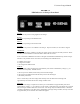
The voltmeter will show battery voltage as soon as the DC connection is completed.
Check the voltmeter
as soon as t
he DC connection has been made. If the meter reads zero or is deflecting below zero, reverse
the polarity of the battery connections.
2.3
Alarm Connections
F3 chargers are supplied with one of three following alarms configurations:
TABLE 2.3
Charger Part Number Suffix and Alarms Configuration
Second digit of part number suffix (e.g. "F
5E2")
Alarms “0”
Alarms “5” Alarms “6” < Alarm system code
Indications
none
Float or boost mode Float or boost mode LED
none
AC fail AC fail LED & Form C contact
none
Charger fail Charger fail LED & Form C contact
none
Low battery voltage Low battery voltage LED & Form C contact
none
High battery voltage High battery voltage LED & Form C contact
none
none Ground fault LED
none
none Ground fault - LED
none
none Ground fault + or - Form C contact
none
Summary of above Summary of above Form C contact
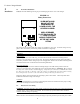
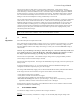
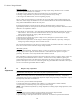
Connect to the charger’s Form C contacts according to Figure 2.3
1. Make connections to the system's Form C alarm contacts as shown.
2. Run alarm wiring out of the charger separately from the AC supply wiring
3. Use 16 to 22
-gauge wire.
4. NOTE: Do not exceed the relay maximum current rating of 0.5A @ 117 VAC or 1A @ 24 VDC.
The remote alarm connection board is located on the circuit breaker pan, adjacent to the control board.
See Figure 2.3 on next page.
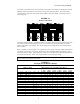
FIGURE 2.3
Remote Contact Terminal Block
FAIL
OK
COM
GROUND
FAULT
AC
FAIL
CHARGE
FAIL
LOW DC
VOLTS
HIGH DC
VOLTS
LOW DC
DISC.
OPTIONSUMMARY
FAIL
OK
COM
FAIL
OK
COM
FAIL
OK
COM
FAIL
OK
COM
FAIL
OK
COM
FAIL
OK
COM
FAIL
OK
COM
2.4
Temperature Compensation
F3 chargers include battery temperature compensation (TC). TC is required by all batteries for maximum
performance and life. The TC feature automatically reduces the charger’
s output voltage at high
temperatures and vice
-versa.