
Operating instructions

F3 Series Charger Manual
5
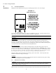
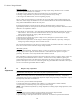
AC and DC connections direct to the AC and DC circuit breakers in accordance with diagram 2.2 below.
Caution:
Small sense leads are connected to the output side of the DC breaker. These must remain
connected to the output side of the
breaker after installation of the DC cabling, or the charger will not
function properly.
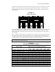
FIGURE 2.2
Power Connections
DC OUTPUT
- +
AC INPUT
ØA ØB ØC
Connection should be made by a qualified installer in accordance with national and local electrical code
s.
The installer should determine the gauge of wire to be used based on the length of cable run and the
ampere requirements of the charger. Size the DC cabling to keep voltage drop in the charging leads as
low as possible.
Refer to TABLE 2.2 for the cha
rger’s AC requirement of your charger. The input voltage and frequency
are marked on the charger’s front panel. Maximum current consumption will be approximately 75% to
80% of the breaker’s rating. Typical efficiency is 85% for 24 volt units, 88% for 48
volt units and 91%+
for 120 and 240 volt units. Power factor is approximately 0.8 at rated input voltage.
WARNING:
The battery charger must be connected to a grounded permanent wiring system. A ground
stud or terminal is provided for this purpose
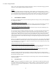
TABLE 2.2
AC Input Circuit Breaker Ratings
Charger output Rated Charger AC Circuit Breaker (/Phase)
208V 240V 380V 400V 415V 480V
V
A V A V A amps amps amps amps amps amps
24
100 48 50 15 15 15 15 15 15
24
150 48 75 20 20 15 15 15 15
24
200 48 100 30 25 15 15 15 15
48 150 40 35 25 25 20 20
48 200 60 50 30 30 30 25
120 25 20 15 15 15 15 15
120 35 25 25 15 15 15 15
120 50 35 35 20 20 20 15
120 75 50 50 30 30 25 25
120 100 70 70 40 35 35 30
168 30 15
96 50 20
110 100 40
144 30 15