F3 SERIES CASE SIZE 3A FILTERED BATTERY CHARGER OPERATION & MAINTENANCE MANUAL SENS part no.: Document revision: DCN number Date 101146 H 106651 9/19/2014 1840 Industrial Circle Longmont, CO 80501 Fax: (303) 678-7504 Tel: (303) 678-7500 Email: service@sensusa.com Web: www.sens-usa.com Installation or Service problems? Call SENS at (800) 742-2326 between 8:00 am and 5:00 pm Mountain time Monday through Friday, or visit our website.
F3 Series Charger Manual IMPORTANT SAFETY INSTRUCTIONS SAVE THESE INSTRUCTIONS This manual contains important safety and operating instructions for Stored Energy Systems (SENS) model F3. Before using the battery charger, read all instructions and cautionary markings on the battery charger, battery and equipment connected to the battery system. WARNING: Please read these safety warnings and heed them. Failure to do so could result in either severe personal injury or equipment damage.
F3 Series Charger Manual 1 This manual covers installation, operation and troubleshooting of SENS model F3 filtered battery charger. Overview 1.1 READ THIS FIRST Please follow the installation and use instructions. They are vital to the satisfactory operation of the charger. If you have any doubts about adjusting, maintaining or servicing the equipment, contact SENS service department. Changing factory-set potentiometers voids the warranty.
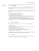
F3 Series Charger Manual 2 2.1 Mechanical Installation Installation Caution: Heed the following warning to prevent damaging the lower cover of the charger! FIGURE 2.1 Lifting Instructions WHEN INSTALLING DO NOT LIFT UNIT FROM MIDDLE OF LOWER COVER - THE COVER WILL BEND. USE A SPREADER PLATE EQUIVALENT TO 1" THICK PLYWOOD ACROSS THE BOTTOM OF THE UNIT WHEN LIFTING The charger can be mounted either on a wall or in a standard 23” relay rack.
F3 Series Charger Manual AC and DC connections direct to the AC and DC circuit breakers in accordance with diagram 2.2 below. Caution: Small sense leads are connected to the output side of the DC breaker. These must remain connected to the output side of the breaker after installation of the DC cabling, or the charger will not function properly. FIGURE 2.
F3 Series Charger Manual Caution: Do NOT connect the battery backwards; charger damage may result The voltmeter will show battery voltage as soon as the DC connection is completed. Check the voltmeter as soon as the DC connection has been made. If the meter reads zero or is deflecting below zero, reverse the polarity of the battery connections. 2.3 Alarm Connections F3 chargers are supplied with one of three following alarms configurations: TABLE 2.
F3 Series Charger Manual The F3 has provision for either local or remote sensing of temperature. Local sensing is done by components located on the charger’s control board, which is exposed to the ambient air. At installations where the battery is located in a different room, or is otherwise subject to ambient temperatures different from the charger it is necessary to sense temperature at the battery. The SENS remote sensor is optional.
F3 Series Charger Manual battery. This is the normal charging position for all batteries, and the recommended charging position at all times for Valve Regulated Lead Acid (VRLA) batteries. BOOST This voltage is slightly higher than the float setting. Boost slightly overcharges the battery in order to ensure that all the cells of a battery are fully charged to the same voltage.
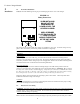
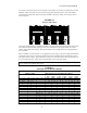
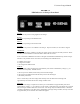
F3 Series Charger Manual FIGURE 3.4 LED Indicators on Charger Front Panel AC ON Indicates that AC power is being supplied to the charger. BOOST The charger is operating in the BOOST mode. FLOAT The charger is operating in the FLOAT mode. AC FAIL Indicates that AC power is not available to the charger. Input AC is failed, or AC breaker is tripped. CHGR FAIL Indicates that the charger is failing to produce the output current required by the battery and load.
F3 Series Charger Manual HIGH DC SHTDN Indicates that the charger has been shut down by the high output voltage shutdown circuit. Probable causes of a high DC shutdown are as follows: a) The float or boost voltages have been increased above the pre-set shutdown voltage b) The high voltage shutdown set point has been changed from the factory setting. c) The charger has malfunctioned, and is not regulating properly.
F3 Series Charger Manual “FLOAT” (R34) and “BOOST” (R33), both located next to one of the control transformers. 4. Adjust the FLOAT pot until the desired voltage is achieved. Adjustment of the BOOST voltage is similar to adjustment of FLOAT, except that you adjust the BOOST pot instead of the FLOAT pot. Be sure that the charger front panel mode switch is in BOOST when you make adjustments. Please note that the BOOST adjustment controls the level above FLOAT voltage, not the absolute voltage.
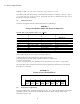
F3 Series Charger Manual CHART 4.2 Graph of Factory-Set Output, Alarm and Shutdown Voltages 2.55 VRLA Float 2.45 VRLA Boost Flooded Float 2.35 Flooded Boost 2.25 HV Alm VRLA 2.15 HV Shtdn VRLA 1.85 HV Alm Flooded 1.75 HV Shtdn Flooded Low DC Alarm Degrees C 4.3 Forced Load Sharing Chargers can be set up for forced load sharing when used in parallel with units of the same current rating.
F3 Series Charger Manual 5 5.1 Troubleshooting Table Troubleshooting If there is a problem and you suspect the charger is at fault, turn off the AC mains supply before proceeding. Ensure that the following are correct: AC input wiring, battery and/or load connections and PC card connectors. Ensure no foreign objects are in charger.
F3 Series Charger Manual Symptom High output volts / High DC alarm Possible Cause Test Corrective Action Line voltage less that charger's specified operating range Control board failure Measure AC line voltage Use larger gauge AC wires or contact utility company Replace with known good board Replace board Adjust pot and see if output voltage is affected Adjust float pot to correct output voltage Misadjusted Float Voltage pot on control board Remote temperature sensor failure Remove Remote Temp
F3 Series Charger Manual Refer to Figure 5.2. Disconnect all the leads to the SCR and its heat sink. Connect a voltmeter across the 1KΩ resistor to measure the voltage drop. With the battery connected as shown, Vdrop should read approximately 2.3V (Vsource-0.7V). Remove the voltage source to the gate, but keep it connected to the 1KΩ resistor and cathode. Vdrop should equal zero. Reconnect the gate and reverse the batteries polarity. Vdrop should read zero volts.
F3 Series Charger Manual 16
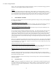
F3 Series Charger Manual Diagram of Automatic Boost Operation (Optional Feature) Appendix Boost v oltage Float v oltage Battery voltage Point at which charger changes f rom current limit to v oltage limit Volts Point at which AUTOBOOST returns charger to f loat v oltage 100% charger output current Charger output current Amps 50% to 75% of charger current limit Zero current f low 0 Time NOTE: When the charger switches f rom BOOST to FLOAT mode, no current will f low into the battery f or a whil
SENS Limited Warranty Policy What is covered: This warranty covers any defect in material and workmanship on battery chargers manufactured by Stored Energy Systems, a Colorado Limited Liability Company (SENS).