
User Manual


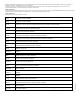
Table Of Contents
- Contents
- 1 About This Getting Started Guide
- 2 Unpacking the ZoneFlex Wireless Bridge
- 3 Before You Begin
- 4 Pre-Installation Configuration
- Summary of Pre-Installation Tasks
- What You Will Need
- Access the Web Interface
- Step 1: Connect the Power and Ethernet Cables
- Step 2: Prepare the Administrative Computer
- Step 3: Connect the Wireless Bridge to the Admin Computer
- Step 4: Log In to the Web Interface
- Step 5: Change the Country Code
- Step 6: Change Optional Configuration Settings
- Step 7: Change Non-Root Bridge Configuration Settings
- Step 8: Test the Link Between the Bridges
- Step 9: Disconnect the Wireless Bridge from the Administrative Computer
- Step 10: Restore the Administrative Computer’s Network Settings
- 5 Provisioning and Associating the Wireless Bridge Pair (Optional)
- 6 Physical Installation
- Prepare the Required Hardware and Tools
- Determine the Optimal Mounting Location and Orientation
- Become Familiar with the Installation Components
- Decide How You Will Supply Power to the Wireless Bridge
- Deploying the Wireless Bridge
- Attaching the Mounting Brackets
- Mounting the Wireless Bridge
- Mounting and Connecting the External Antenna (Optional)
- 7 Aiming the Bridge Pair
- 8 Verifying the Connection
- 9 What to Do Next

57
Aiming the Bridge Pair
Mounting and Connecting the External Antenna (Optional)
4. Ensure that antenna connectors are firmly tightened, and apply weatherproofing tape
to the antenna connectors to help prevent water from entering the connectors.
5. Reconn
ect the Wireless Bridge to the power source.
CAUTION: If you are not connecting external antennas to the Wireless Bridge, make sure
that the metal caps remain installed and securely fastened to protect the interface from
elements, such as water or dirt.
You have completed connecting the external antenna to the Wireless Bridge.
7 Aiming the Bridge Pair
Once both units are installed in their permanent locations, press the Aiming Button on
the outside of either unit to begin aiming. Alternatively, you can start the aiming process
via the Web browser, by clicking Start Aiming on the Status > Wireless page.
1. Pr
ess the blue button on the side of either bridge and hold it for 4 seconds.
• The bottom LED turns yellow, indicating that the unit is in Aiming Mode.
• If the unit is in Aiming mode but there i
s no association between the two bridge
units, all LEDs will cycle yellow until the two ZoneFlex 7731 units have associated.
2. Adjust the azim
uth and elevation of the first unit to maximize the Aiming LED indica-
tors. RSSI (received signal strength indication) values are shown in
Tabl e 6 .
Table 6. RSSI values of LED indicators
LED Status RSSI (<=)
LED 6
Solid 35 (Max)
Flashing 30
LED 5
Solid 28
Flashing 25
LED 4
Solid 23
Flashing 20
LED 3
Solid 18
Flashing 15
LED 2
Solid 13
Flashing 10
LED 1
Solid 8
Flashing 5 (Min)