Wireless-N Pocket AP/Router ETR9360 Wireless-N Pocket AP/Router V1.
1 1. Package Contents ......................................................................................................................................................4 2. System Requirements ................................................................................................................................................4 3. Introduction....................................................................................................................................................
2 8.2.6 Tools ................................................................................................................................................100 8.3 AP and Client Bridge Modes........................................................................................................................108 8.4 Client Bridge Mode ......................................................................................................................................113 8.4.1 Wireless..................
3 Revision History Version 1.
4 1. Package Contents • • • • • • EnGenius TRAVEL ROUTER Li-ion Battery AC Adapter RJ-45 Ethernet LAN Cable CD-ROM with User Manual and Setup Utility Quick Guide 2.
5 3. Introduction TRAVEL ROUTER is the world’s smallest 11n Wireless Router and Access Point connectivity that brings superior convenience for users who need to create a wireless network to share the Internet, documents or multimedia files quickly between computers at speeds of up to 150Mbps. Also, you can leave the bulky power adapter behind as the power supply unit is embedded in the device, so it can be slipped into your pocket easily.
6 4. Features • WORLD’S SMALLEST AP Superior design to bring you the world’s smallest 11n AP Router for a true portable wireless solution. • INTERNAL POWER No need to bring bulky power adapters for improved space saving convenience. •INTERNET SHARING Wirelessly share your Internet connection to multiple computers. • Multiple OPERATION MODES AP Router, Access Point and Client Bridge modes for flexible usage in different scenarios. • 802.11n COMPLIANT Fully 802.
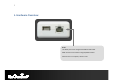
7 5. Hardware Overview RJ-45 This RJ-45 port can be configured as WAN or LAN modes. WAN: Connect to the Internet using DSL/Cable modem. LAN: Connect to a computer, switch or hub.
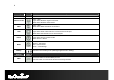
8 LED Lights Description icon Color – Blue Lights when Wireless signal is activated. Blinks when Wireless data transfer. Wireless LAN WPS Color – Blue Blinks when WPS handshake is initialized. LAN Color – Blue Lights when wired network device is connected to RJ-45 port. Blinks when data transfer occurs on RJ-45 port. Power Color – Blue Lights when device is powered ON. Blinks device is Reset. Mode Indicates which mode the TRAVEL ROUTER is set to.
9 6. Before you Begin This section will guide you through the installation process. Placement of the TRAVEL ROUTER is very important to avoid poor signal reception and performance. Avoid placing the device in enclosed spaces such as a closet, cabinet or wardrobe. 6.1 Considerations for Wireless Installation The operating distance of all wireless devices cannot be predetermined due to a number of unknown obstacles in the environment that the device is deployed.
10 6.2 AP Router / AP / Client Bridge Modes There are three main modes to select from which will influence the installation of the TRAVEL ROUTER. This section will help you determine which mode works with your setup. AP Router Mode AP Router Mode allows you to share an Internet connection to multiple computers. AP Mode AP mode establish a network with the Access Point. It does not have NAT function and the ability connecting to internet.
11 6.3 Computer Settings (Windows XP/Vista) 1. Click Start button and open Control Panel.
12 2. Windows XP, click [Network Connection] Windows Vista, click [View Network Status and Tasks] then [Manage Network Connections] 3. Right click on [Local Area Connection] and select [Properties].
13 4. Check “Client for Microsoft Networks”, “File and Printer Sharing”, and “Internet Protocol (TCP/IP) is ticked. If not, please install them. 5. Select “Internet Protocol (TCP/IP)” and click [Properties] 6. Select “Obtain an IP Address automatically” and “Obtain DNS server address automatically” then click [OK].
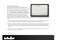
14 7. Hardware Installation CHARGE THE BATTERY Slide to open the battery cover and insert the battery into place. Insert the battery as shown below.
15 Please lay the device safely on flat surface while charging. Make sure on/off switch is flipped to “O” sign and plug in the included adapter (DC-IN) to start charging the battery. Red light indicates low in battery. It’s recommended to fully charge the battery before use.
16 POWER ON Recommended uses the device after fully charged the battery. Make sure On/Off switch is flipped to the “I” sign. Please wait after Wireless starts blinking. Note1: Please flip on/off switch to “O” when charging the battery. Note2: It takes about 2 hours to fully charge the battery.
17 AP Router Mode: One type of Internet connection is required. Please either connect the network cable from your DSL/Cable modem to the RJ-45 port on the TRAVEL ROUTER.
18 AP Mode: Connect the network cable to the RJ-45 port.
19 8. Configuring Travel Router This section will show you how to configure the device using the web-based configuration interface. Please use your wireless network adapter to connect the TRAVEL ROUTER. Default Settings IP Address 192.168.0.1 Username / Password admin / admin Wireless Mode Enable EnGeniusxxxxxx Wireless SSID Wireless Security None Note: xxxxxx represented in the wireless SSID above is the last 6 characters of your device MAC Address.
20 8.1 Setup Wizard 1. Open a web browser (Internet Explorer/Firefox/Safari) and enter the IP Address http://192.168.0.1 Note: If you have changed the default LAN IP Address of the TRAVEL ROUTER, ensure you enter the correct IP Address. 2. The default username and password are admin. Once you have entered the correct username and password, click the OK button to open the web-base configuration page.
21 3. You will see the following webpage if login successful. 4. Click Wizard to enter the Setup Wizard. Then click Next to begin the wizard.
22 ETR9360
23 5. Select the Operation Mode. Please ensure you have the proper cables connected as described in the Hardware Installation section.
24 8.1.1 AP Router Mode a) The device will now automatically search for the correct Internet settings. b) The most appropriate WAN type will be determined and selected automatically. If it is incorrect, please select Others to set up the WAN settings manually.
25 c) There are many WAN service types available. Please obtain the correct settings from your Internet Service Provider (ISP). Static IP Address If your ISP Provider has assigned you a fixed IP address, enter the assigned IP address, Subnet mask, Default Gateway IP address, and Primary DNS and Secondary DNS (if available) of your ISP provider.
26 Dynamic IP Address The IP Address is allocated automatically. However some ISP’s will also recognize the MAC address and will reject connections if the MAC address does not match. If your ISP has recorded the MAC address of your computer’s Ethernet LAN card, please connect only the computer with the authorized MAC address, and click the Clone MAC Address button. This will replace the AP Router MAC address to the computer MAC address. The correct MAC address is used to initiate the connection to the ISP.
27 PPP over Ethernet ISP requires an account username and password. PPP over Ethernet Username: Username assigned to you by the ISP Password: Password for this username. Service: You can assign a name for this service. (Optional) MTU: The maximum size of packets. Do not change unless mentioned by the ISP.
28 Point-to-Point Tunneling Protocol (PPTP) PPTP is used by some ISPs.
29 PPTP WAN Interface Settings WAN Interface Type: Select whether the ISP is set to Static IP or Dynamic IP addresses. Hostname: This is optional. Only required if specified by ISP MAC: The MAC Address that is used to connect to the ISP. PPTP Settings Login: Username assigned to you by the ISP Password: Password for this username. Service IP Address: The IP Address of the PPTP server. Connection ID: This is optional. Only required if specified by ISP MTU: The maximum size of packets.
30 Layer-2 Tunneling Protocol (L2TP)
31 L2TP WAN Interface Settings WAN Interface Type: Select whether the ISP is set to Static IP or Dynamic IP addresses. Hostname: This is optional. Only required if specified by ISP MAC: The MAC Address that is used to connect to the ISP. L2TP Settings Login: Username assigned to you by the ISP Password: Password for this username. Service IP Address: The IP Address of the PPTP server. MTU: The maximum size of packets. Do not change unless mentioned by the ISP.
32 d) Setup the level of wireless security to be used. EnGenius recommends the Highest level of security to be used. Note: 802.11n wireless speeds may not be achievable if the security is setup to Lowest and Low level. SSID: Enter the name of your wireless network. Key: Enter the security key for your wireless network.
33 e) Check the settings are correct, and then click Reboot to apply the settings.
34 8.1.2 AP Mode a) Select the level of wireless security to be used. EnGenius recommends the Highest level of security to be used. Note: 802.11n wireless speeds may not be achievable if the security is setup to Lowest and Low level. SSID: Enter the name of your wireless network. Key: Enter the security key for your wireless network.
35 b) Check the settings are correct, and then click Reboot to apply the settings.
36 8.1.3 Client Bridge Mode a) In this mode, the TRAVEL ROUTER will connect to a wireless network as a client device. Please enter the SSID and security settings of that wireless network. b) Check the settings are correct, and then click Reboot to apply the settings.
37 8.2 Web-Based Configuration 8.2.1 System Status This page allows you to monitor the status of the device.
38 Status Model: Description of this device. Mode: The device is currently in which mode. Uptime: The duration about the device has been operating without powering down or reboot. Current Date/Time: The device’s system time. If this is incorrect, please set the time in the Tools / Time page. Hardware version and Serial Number: Hardware information for this device. Kernel and Application version: Firmware information for this device.
39 WAN Settings Attain IP Protocol: Method used to connect to the Internet IP address: The WAN IP Address of the device. Subnet Mask The WAN Subnet Mask of the device. MAC address The MAC address of the device’s WAN Interface. Primary and Secondary DNS: Primary and Secondary DNS servers assigned to the WAN connection.
40 LAN Settings IP address: The LAN IP Address of the device. Subnet Mask The LAN Subnet Mask of the device. DHCP Server Whether the DHCP server is Enabled or Disabled. WLAN Settings Channel: The wireless channel in use. ESSID: The SSID (Network Name) of the wireless network. (up to 4 SSID’s are supported) Security: Wireless encryption is enabled for this SSID. BSSID: The MAC address of this SSID. Associated Clients: The number of wireless clients connected to this SSID.
41 LAN This page allows you to modify the device’s LAN settings.
42 LAN IP IP address: The LAN IP Address of this device. IP Subnet Mask: The LAN Subnet Mask of this device. 802.1d Spanning Tree: When Enabled, the Spanning Tree protocol will prevent network loops in your LAN network.
43 DHCP Server DHCP Server: The DHCP Server automatically allocates IP addresses to your LAN devices. Lease Time: The duration of the DHCP server allocates each IP address to a LAN device. Start / End IP: The range of IP addresses of the DHCP server will allocate to LAN devices. Domain name: The domain name for this LAN network.
44 Two DNS servers can be assigned for use by your LAN devices. There are four modes available. DNS Servers From ISP: The DNS server IP address is assigned from your ISP. User-Defined: The DNS server IP address is assigned manually. DNS Relay: LAN clients are assigned the device’s IP address as the DNS server. DNS requests are relayed to the ISP’s DNS server.
45 DHCP This page shows the status of the DHCP server and also allows you to control how the IP addresses are allocated.
46 The DHCP Client Table shows the LAN clients that have been allocated an IP address from the DHCP Server . DHCP Client Table IP address: The LAN IP address of the client. MAC address: The MAC address of the client’s LAN interface. Expiration Time: The time that the allocated IP address will expire. Refresh: Click this button to update the DHCP Client Table.
47 You can also manually specify the IP address that will be allocated to a LAN client by associating the IP address with its MAC address. Type the IP address you would like to manually assign to a specific MAC address and click Add to add the condition to the Static DHCP Table.
48 Schedule This page allows you to schedule times that the Firewall and Power Saving features will be activated / deactivated. Click Add to create a Schedule entry.
49 Schedule Schedule Description: Assign a name to the schedule. Service: The service provides for the schedule. Days: Define the Days to activate or deactivate the schedule. Time of day: Define the Time of day to activate or deactivated the schedule. Please use 24-hour clock format.
50 Log This page displays the system log of the device. When powered down or rebooted, the log will be cleared. Log Save: Save the log to a file. Clear: Clears the log. Refresh: Updates the log.
51 Monitor This page shows a histogram of the WAN and Wireless LAN traffic. The information is automatically updated every five seconds.
52 Language This page allows you to change the Language of the User Interface.
53 8.2.2 Internet The Internet section allows you to manually set the WAN type connection and its related settings. Status This page shows the current status of the device’s WAN connection.
54 Dynamic IP Address The IP Address is allocated automatically. However some ISP’s will also recognize the MAC address and will reject connections if the MAC address does not match. If your ISP has recorded the MAC address of your computer’s Ethernet LAN card, please connect only the computer with the authorized MAC address, and click the Clone MAC Address button. This will replace the AP Router MAC address to the computer MAC address. The correct MAC address is used to initiate the connection to the ISP.
55 Dynamic IP Address Hostname: This is optional. Only required if specified by ISP MAC address: The MAC Address that is used to connect to the ISP. DNS Servers Two DNS servers can be assigned for use by your LAN devices. There are two modes available. From ISP: LAN devices are assigned the DNS server IP address of your ISP. User-Defined: Set the DNS server IP address manually.
56
57 PPP over Ethernet ISP requires an account username and password.
58 PPP over Ethernet (PPPoE) Username: Username assigned to you by the ISP Password: Password for this username. Service: You can assign a name for this service. (Optional) MTU: The maximum size of packets. Do not change unless mentioned by the ISP. Authentication type Select whether the ISP uses PAP or CHAP methods for authentication. Select Auto if unsure. Type: You can choose the method that the router maintains connection with the ISP.
59 Point-to-Point Tunneling Protocol (PPTP) PPTP is used by some ISPs.
60 Point-to-Point Tunneling Protocol (PPTP) WAN Interface Type: Select whether the ISP is set to Static IP or will allocate Dynamic IP addresses. Hostname: This is optional. Only required if specified by ISP MAC address: The MAC Address that is used to connect to the ISP. Login: Username assigned to you by the ISP Password: Password for this username. Service IP Address: The IP Address of the PPTP server. Connection ID: This is optional.
61 Layer-2 Tunneling Protocol (L2TP) L2TP is used by some ISPs.
62 Layer-2 Tunneling Protocol (L2TP) WAN Interface Type: Select whether the ISP is set to Static IP or will allocate Dynamic IP addresses. Hostname: This is optional. Only required if specified by ISP MAC: The MAC Address that is used to connect to the ISP. Login: Username assigned to you by the ISP Password: Password for this username. Service IP Address: The IP Address of the PPTP server. MTU: The maximum size of packets. Do not change unless mentioned by the ISP.
63 8.2.3 Wireless The Wireless section allows you to configure the Wireless settings. Status This page shows the current status of the device’s Wireless settings.
64 Basic Radio: Enable or Disable the device’s wireless signal. Mode: Select between Access Point or Wireless Distribution System (WDS) modes. Band: Select the types of wireless clients that the device will accept. eg: 2.4 GHz (B+G) Only 802.11b and 11g clients will be allowed. Enable SSID#: Select the number of SSID’s (Wireless Network names) you would like. You can create up to 4 separate wireless networks. SSID# Enter the name of your wireless network. You can use up to 32 characters.
65 Wireless Distribution System (WDS) Using WDS to connect Access Point wirelessly, and in doing so extend a wired infrastructure to locations where cabling is not possible or inefficient to implement. Note that compatibility between different brands and models is not guaranteed. It is recommended that the WDS network be created using the same models for maximum compatibility. Also note that all Access Points in the WDS network needs to use the same Channel and Security settings.
66 Advanced This page allows you to configure wireless advance settings. It is recommended the default settings are used unless the user has experience with these functions.
67 Advanced Fragment Threshold: Specifies the size of the packet per fragment. This function can reduce the chance of packet collision. However when this value is set too low, there will be increased overheads resulting in poor performance. RTS Threshold: When the packet size is smaller than the RTS Threshold, then the packet will be sent without RTS/CTS handshake which may result in incorrect transmission. Beacon Interval: The time interval that the device broadcasts a beacon.
68 Security This page allows you to set the wireless security settings.